

Remote entrance guard terminal
A door guard and remote technology, applied in the field of remote door guard terminals, can solve the problems of poor security protection effectiveness, high cost, and high cost of door guard personnel in the automatic anti-theft alarm system
- Summary
- Abstract
- Description
- Claims
- Application Information
AI Technical Summary
Problems solved by technology
Method used
Image

Examples
Embodiment Construction
[0039] The present invention will be further described below in conjunction with accompanying drawing.
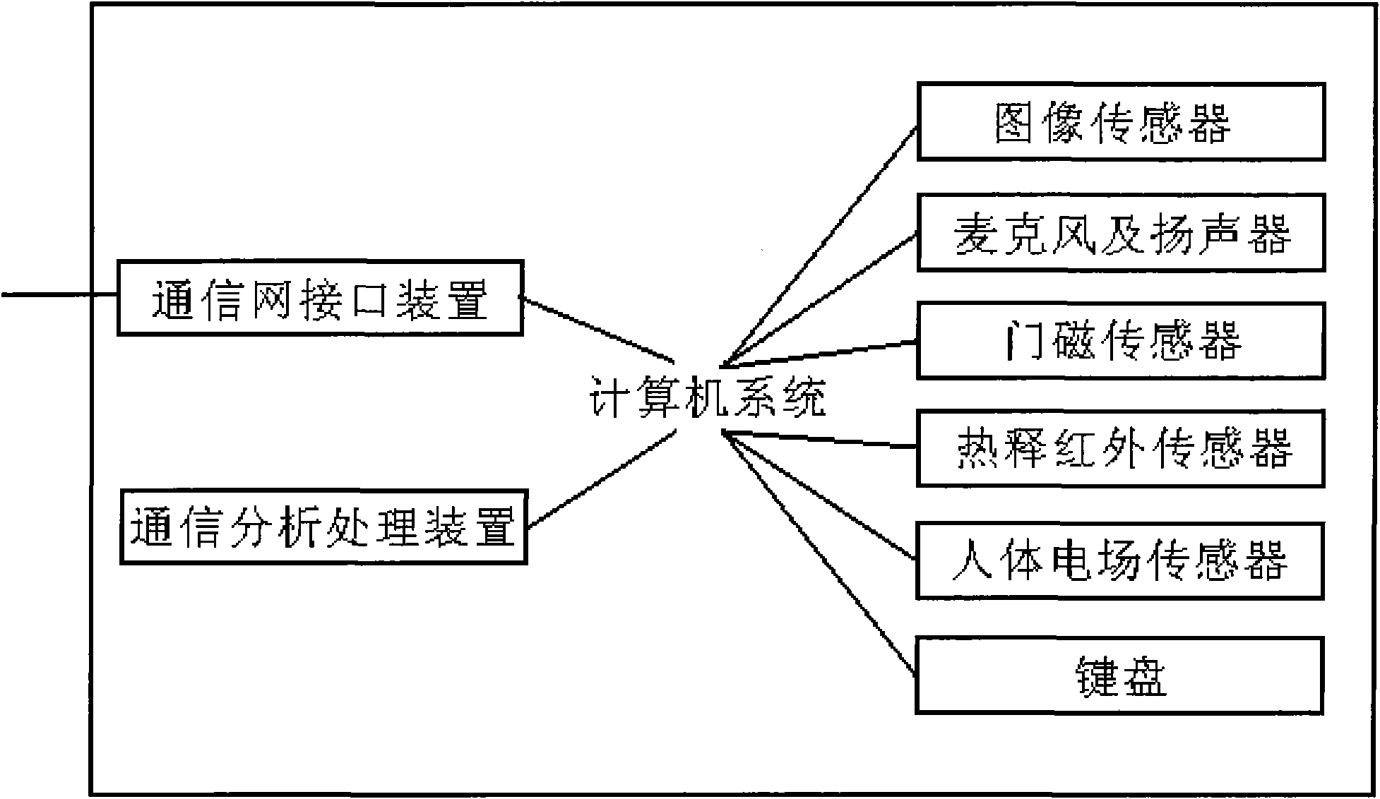
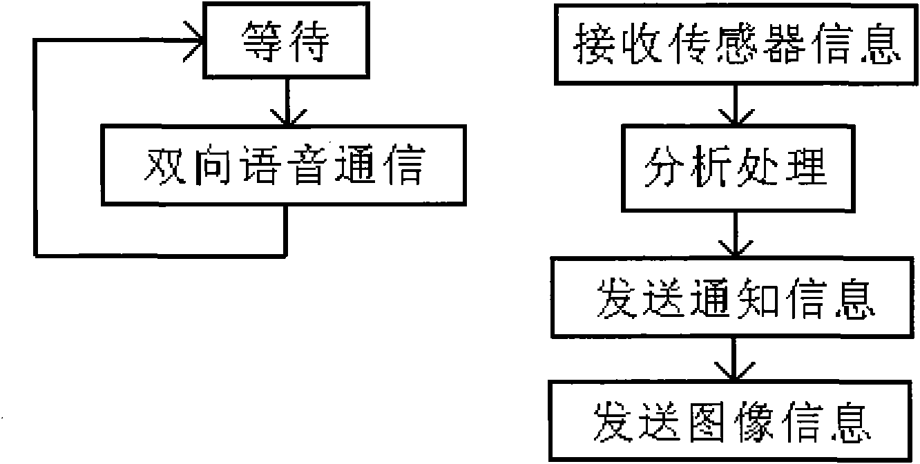
[0040] like figure 1 and figure 2 Shown, a kind of remote doorman terminal, comprises computer system, comprises the communication network interface device that is connected with described computer system, comprises (coming person or image) sensor and microphone and loudspeaker that are connected with described computer system, and described computer The system also includes a communication analysis and processing device composed of computer-specific software, which is characterized in that the function of realizing the software program flow of the communication processing device is:
[0041] Function 1. Receive and determine whether there are people coming from the sensor site;
[0042] Function 2. When there is a visitor on the site, send a visitor notification message to the remote door guard service system;
[0043] Function 3. Send on-site image information to the ...
PUM
 Abstract
Description
Claims
Application Information