Drive circuit for controlling electric energy of light source, method and system

A technology of driving circuit and dimming controller, which is applied in the direction of electric lamp circuit layout, light source, electric light source, etc., and can solve the problem that users cannot adjust the brightness

A technology of driving circuit and dimming controller, which is applied in the direction of electric lamp circuit layout, light source, electric light source, etc., and can solve the problem that users cannot adjust the brightness

CN101854759BInactive Publication Date: 2011-07-06AOTU ELECTRONICS WUHAN

Image

  • Drive circuit for controlling electric energy of light source, method and system
  • Drive circuit for controlling electric energy of light source, method and system
  • Drive circuit for controlling electric energy of light source, method and system

Examples


Embodiment Construction

[0023] Detailed reference will be given below to examples of the present invention. Although the present invention has been illustrated and illustrated by these embodiments, it should be noted that the present invention is not limited to these embodiments. On the contrary, the invention covers all alternatives, modifications and equivalents which are within the spirit and scope of the invention as defined by the appended claims.

[0024] In addition, in order to better illustrate the present invention, numerous specific details are given in the specific embodiments below. It will be understood by those skilled in the art that the present invention may be practiced without these specific details. In other instances, well-known methods, procedures, components and circuits have not been described in detail so as not to obscure the gist of the present invention.

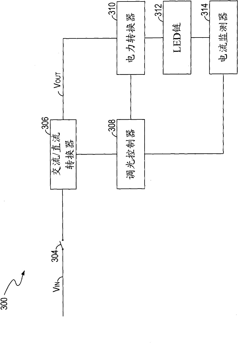
[0025] image 3 Shown is a block diagram of a light source driving circuit 300 according to one embodiment of the p...


PUM


Abstract

The invention discloses a drive circuit for controlling electric energy of a light source, a method and a system. The drive circuit comprises a power convertor which is respectively connected with a power supply and a light source and a dimming controller connected with the power convertor; the power convertor receives the electric energy from the power supply and supplies an electric energy after adjustment for the light source; the power convertor includes a control switch in serial connection with the light source; the dimming controller monitors the power switch between the power supply and the drive circuit and receives the dimming request signal and the dimming stop signal; the dimming request signal indicates the first group of actions of the power switch and the dimming stop signal indicates the second group of actions of the power switch. If receiving the dimming request signal, the dimming controller controls the control switch to continuously adjust the electric energy which is output from the power convertor after adjustment; and if receiving the dimming stop signal, the dimming controller stops the electric energy which is output from the power convertor after adjustment.

Description

technical field [0001] The invention relates to a driving circuit, a method and a system for controlling electric energy of a light source. Background technique [0002] In recent years, new light sources such as light-emitting diodes (LEDs) have advanced both in materials and manufacturing. LED has the characteristics of high efficiency, long life, bright colors, etc., and can be used in the fields of automobiles, computers, communications, military and daily necessities. For example, LED lamps can replace traditional incandescent lamps as lighting sources. [0003] figure 1 Shown is a schematic diagram of a conventional LED driving circuit 100 . LED driver circuit 100 utilizes LED chain 106 as a light source. LED chain 106 includes a plurality of LEDs connected in series. The power converter 102 is used to convert the DC input voltage Vin into a desired DC output voltage Vout for powering the LED chain 106 . A switch 104 connected to the power converter 102 can conne...

Claims


Application Information

Patent Timeline
06 Jul 2011
Publication
CN101854759B
IPC
H05B37/02
Inventors
郭清泉; ζž—ζ°Έιœ–