Unattended digital multi-well automatic metering device and method

An automatic metering, multi-well technology, applied in the field of metering, can solve the problems of complex process and difficult operation, and achieve the effect of good separation effect, simple structure and fast speed.

Inactive Publication Date: 2013-04-17
濮阳圣元火炬工程有限公司
View PDF6 Cites 0 Cited by
  • Summary
  • Abstract
  • Description
  • Claims
  • Application Information

AI Technical Summary

Problems solved by technology

[0002] At present, most of the oil and gas wells in the oil and gas fields are manned on duty for on-duty measurement and alarm; the process of gas-liquid separation and oil-water separation is complex and difficult to operate

Method used


Image

  • Unattended digital multi-well automatic metering device and method

Examples


Embodiment Construction

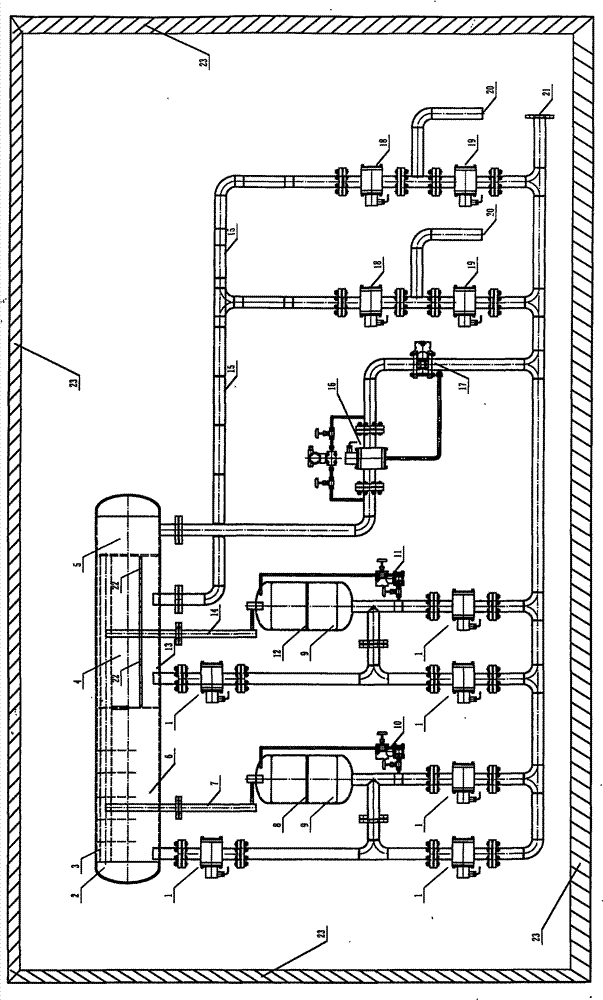
[0007] exist figure 1 Among them, the three-phase piston separator 2 and the manifold valve line are installed in the constant temperature anti-theft metering room 23. One end of the three-phase piston separator 2 is a separation air chamber 5, and the middle is a separation oil chamber 4 and a separation water chamber 13. One end is an oil-gas high-efficiency separation chamber 6, and there is an air guide pipe 3 on the top of the three-phase piston separator 2, and the air guide pipe 3 is connected to the separation air chamber 5; one end of the feed pipe 15 is connected to the discharge pipe, and a manifold is installed in the middle The metering valve 18 at the upper end and the confluence valve 19 at the lower end of the manifold. There is a metering medium inlet 20 between the metering valve 18 at the upper end of the manifold and the confluence valve 19 at the lower end of the manifold. The metering valve 18 at the upper end of the manifold and the confluence valve 19 a...


PUM


Abstract

The invention relates to an unattended digital multi-well automatic metering device and an unattended digital multi-well automatic metering method, which belong to metering technology and overcome the defects of other technology. A triphase piston separator, a pipeline, a piston liquid meter and pipe valves are arranged in a constant-temperature theftproof metering room. The metering process of the method comprises gas-liquid separation, piston oil-water separation, liquid-free gas metering, piston type water metering, piston type oil metering and balanced conflux output.

Description

technical field [0001] The invention relates to a metering technology, in particular to an unattended digital multi-well automatic metering device and a metering method. Background technique [0002] At present, most of the oil and gas wells in the oil and gas fields are manned on duty for on-duty measurement and alarm; the gas-liquid separation and oil-water separation are complicated and difficult to operate. Contents of the invention [0003] The purpose of the present invention is to provide an unattended digital multi-well automatic metering device and metering method with simple structure and convenient operation, which overcomes the shortcomings of other technologies. The purpose of the present invention is achieved in this way. The three-phase piston separator and manifold valve lines are installed inside. One end of the three-phase piston separator is a separation air chamber, the middle is a separation oil chamber and a separation water chamber, and the other end...

Claims


Application Information

Patent Timeline
Patent Type & Authority Patents(China)
IPC IPC(8): E21B47/00E21B43/34
Inventor 李亚强
Owner 濮阳圣元火炬工程有限公司
Why Eureka
Try Eureka