Composite structure of radiator fan and molding method thereof

A heat dissipation fan and combined structure technology, applied in the direction of cooling/ventilation/heating transformation, non-variable pumps, pump devices, etc., can solve problems such as poor smoothness, high difficulty in implementing precise positioning, and high noise, and achieve Combined positioning accuracy improvement effect

Active Publication Date: 2011-05-18
SUZHOU FORCECON ELECTRIC
View PDF6 Cites 7 Cited by
  • Summary
  • Abstract
  • Description
  • Claims
  • Application Information

AI Technical Summary

Problems solved by technology

[0002] In the existing heat dissipation fan, if the shaft center is set on the rotor hub side, there are many parts that are prone to fit errors, such as the fit error between the shaft center and the rotor hub, the fit error between the rotor magnet ring and the stator coil, the shaft The matching error between the core and the stator bearing, the matching error between the stator bearing and the shaft seat, etc., based on this, in the specific manufacturing process of this kind of cooling fan, there is often excessive noise due to the difficulty in implementing precise positioning. Big Problems and Disadvantages
[0003] In view of this, the industry has developed a reverse-shaft cooling fan. The structure of this type of cooling fan is designed because the root of the rotor shaft is reversed and combined with the stator seat, so the shaft and the stator base It is easier to achieve precise vertical accuracy between them. However, because the coil group of the stator is usually combined in a single module form on the pre-formed convex part of the stator base, after its combination, it is easy to have an excessive gap between the axis and the axis. Therefore, after the rotor and the stator are assembled, it is difficult to achieve the positive position between the coil group of the stator and the magnet ring of the rotor, so that there are still problems of poor smoothness and excessive noise during operation.

Method used


Image

  • Composite structure of radiator fan and molding method thereof
  • Composite structure of radiator fan and molding method thereof
  • Composite structure of radiator fan and molding method thereof

Examples


Embodiment

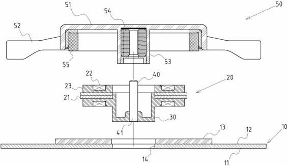
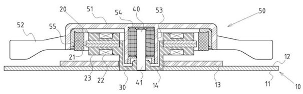
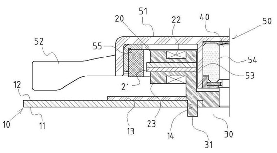
[0025] Example: see attached figure 1 , 2 As shown, the combined structure of the cooling fan includes:

[0026] A base plate 10, which can be a metal plate body, includes a mounting surface 11 and a stator installation surface 12, and a circuit board 13 is arranged on the stator installation surface 12;

[0027] A stator nest positioning part 14 is provided at the center of the stator mounting surface 12 of the base plate 10;

[0028] A stator group 20, including a plurality of silicon steel sheets 21, coils 22 and a plastic insulating frame 23, the plastic insulating frame 23 wraps the silicon steel sheet 21 to shape;

[0029] A plastic composite seat 30 integrally formed on the stator group 20, the plastic composite seat 30 is integrally protruded from the center of the plastic insulating frame 23 of the stator group 20, and the shape of the plastic composite seat 30 can be The sub-seat positioning part 14 is set in the center of the stator installation surface 12 of the...


PUM


Abstract

The invention discloses a composite structure of a radiator fan and a molding method thereof. The composite structure of the radiator fan is characterized by comprising a base plate, a stator insertion seat positioning part, a stator group, a plastic combined seat part, an axle center and a rotor blade group, wherein the base plate comprises an attached surface and a stator assembly surface; the stator insertion seat positioning part is arranged in the center of the stator assembly surface; the stator group comprises silicon steel sheets, coils and a plastic insulating frame seat; the plastic combined seat part is integrally formed on the stator group, and can be inserted, connected and matched with the stator insertion seat positioning part; the axle center is connected to the plastic combined seat part, and has a root fixedly connected to the center of the plastic combined seat part; and the rotor blade group comprises a hub, blades, a shaft sleeve, a bearing component and magnetic rings. The axle center is integrally assembled on the plastic structure of the stator group, and a composite design is adopted between the stator group and the base plate, so precise positioning between the axle shaft and the silicon steel sheets and coils of the stator group can be easily realized by the planning design of an extrusion mould. Therefore, the composite structure of the radiator fan can achieve great improvements in combination and position correction accuracy, is smoother to run and has the advantages of effectively reducing noises, along with practicability and progressiveness.

Description

technical field [0001] The invention relates to a heat dissipation fan, in particular to an innovative design of a combined structure of a rotor and a stator of a heat dissipation fan and a forming method. Background technique [0002] In the existing heat dissipation fan, if the shaft center is set on the rotor hub side, there are many parts that are prone to fit errors, such as the fit error between the shaft center and the rotor hub, the fit error between the rotor magnet ring and the stator coil, the shaft The matching error between the core and the stator bearing, the matching error between the stator bearing and the shaft seat, etc., based on this, in the specific manufacturing process of this kind of cooling fan, there is often excessive noise due to the difficulty in implementing precise positioning. Big problems and drawbacks. [0003] In view of this, the industry has developed a reverse-shaft cooling fan. The structure of this type of cooling fan is designed beca...

Claims


Application Information

Patent Timeline
IPC IPC(8): F04D25/08H05K7/20
Inventor 饶振奇张良升吴添进雷圣奇
Owner SUZHOU FORCECON ELECTRIC
Why Eureka
Try Eureka