Method and device for removing iron in fluid

A fluid and fluid outlet technology, applied in the field of magnetic separation methods and devices, can solve the problems of large clean water, consumption, and poor cleaning effect, and achieve the effects of convenient and reliable use, low manufacturing cost, and recovery ability

Inactive Publication Date: 2011-09-14
李泽
View PDF5 Cites 8 Cited by
  • Summary
  • Abstract
  • Description
  • Claims
  • Application Information

AI Technical Summary

Problems solved by technology

The existing technology is to remove the soft magnetic medium from the magnetic field first, and then clean the ferromagnetic material on the soft magnetic medium by washing. This method requires a lot of cleaning water, and the cleaning process produces The amount of wastewater is relatively large, and secondly, the cleaning effect on the ferromagnetic substances hidden deep in the soft magnetic medium (such as soft magnetic steel wool) is very poor, and it is difficult to clean them out, so that the soft magnetic medium The ability to remove ferromagnetic substances is significantly reduced

Method used


Image

  • Method and device for removing iron in fluid
  • Method and device for removing iron in fluid
  • Method and device for removing iron in fluid

Examples


Embodiment 1

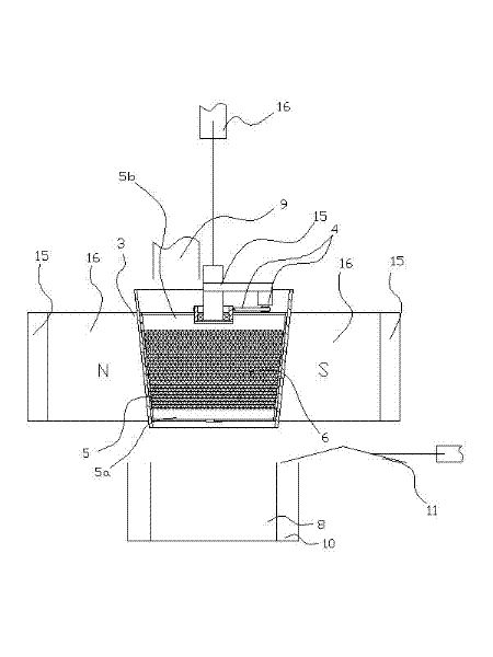
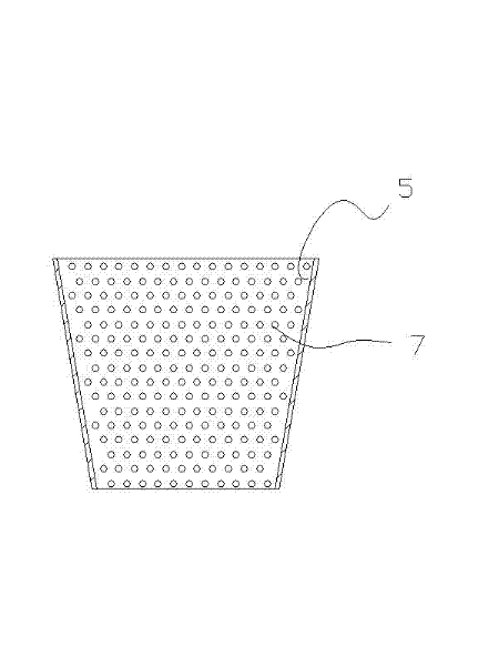
[0025] Embodiment 1: as figure 1 , 2 As shown, the fluid iron removal device of the present invention is realized in this way, comprising the magnetic field 1 formed between the north and south permanent magnet poles 16 with armor 15, the passage 3 arranged in the magnetic field, the passage 3 arranged in the passage 3 with The non-magnetic conductive cylinder 5 of the rotating power mechanism 4, the soft magnetic medium 6, the frame 15, and the lifting power mechanism 16 arranged in the non-magnetic conductive cylinder 5, the passage 3 is conical and non-magnetic, and the corresponding non-magnetic conductive cylinder 5 is conical, and the non-magnetic conductive cylinder 5 is rotated and arranged on the frame 15, and the frame 15 is connected with the lifting power mechanism 16, such as image 3 As shown, several perforations 7 are arranged on the sides of the non-magnetic cylinder 5, and the perforations 7 are distributed in the form of a net on the sides of the non-magnet...

Embodiment 2

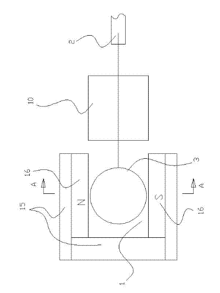
[0029] Embodiment 2: as Figure 4 , 5 , 3, on the basis of embodiment 1 during the present embodiment, the channel 3 is a straight cylindrical non-conductive channel 3 driven in and out of the magnetic field 1 by the overpower mechanism 2, and the non-magnetic tube 5 is arranged on the straight cylindrical non-conductive There is a straight cylindrical non-magnetic conductive cylinder 5 with a rotary power mechanism 4 in the magnetic passage 3, and the diameter of the straight cylindrical nonmagnetic conductive passage 3 is larger than the outer diameter of the straight cylindrical nonmagnetic conductive cylinder 5. In the straight cylindrical nonmagnetic conductive passage 3 A support frame 17 is arranged inside, and the straight cylindrical non-magnetic conduction cylinder 5 is rotatably arranged on the support frame 17, such as Figure 5 As shown, several perforations 7 are arranged on the sides of the non-magnetic cylinder 5, and the perforations 7 are distributed in a me...

Embodiment 3

[0032] Embodiment 3: as Image 6 As shown, this embodiment is based on Embodiment 1, and uses electromagnetic poles to replace the north-south permanent magnet poles 16 .


PUM


Abstract

The invention relates to a method and a device for removing iron in fluid, and the device is characterized by comprising a magnetic field formed by a permanent magnet or an electromagnetic south magnetic pole and an electromagnetic north magnetic pole, a non-magnetic cylinder with a rotary power mechanism, a soft magnetic medium arranged in the non-magnetic cylinder and a channel with a cavity being larger than the non-magnetic cylinder, wherein a plurality of through holes are arranged on the peripheral side surfaces of the non-magnetic cylinder, a fluid collecting groove is arranged on the outer surface of the magnetic field, which is dead against a fluid outlet at the other end of the non-magnetic cylinder, a fluid introduction port is arranged on the outer surface of the magnetic field, which is dead against a fluid inlet at one end of the non-magnetic cylinder, and a ferromagnetic substance collecting groove is arranged at a ferromagnetic substance outlet at the end part of the channel. Compared with the prior art, the device has the advantages of effectively recovering the capability of removing ferromagnetic substances of the soft magnetic medium, being convenient and reliable to use, being simple in structure, and being low in manufacturing cost.

Description

technical field [0001] The invention relates to a magnetic separation method and device. Background technique [0002] The problem to be solved in the existing technology of absorbing ferromagnetic substances in the flowing fluid through the soft magnetic medium arranged between the north and south magnetic poles is to clean the soft magnetic medium filled with ferromagnetic substances. The existing technology is to remove the soft magnetic medium from the magnetic field first, and then clean the ferromagnetic material on the soft magnetic medium by washing. This method requires a lot of cleaning water, and the cleaning process produces The amount of wastewater is relatively large, and secondly, the cleaning effect on the ferromagnetic substances hidden deep in the soft magnetic medium (such as soft magnetic steel wool) is very poor, and it is difficult to clean them out, so that the soft magnetic medium The ability to remove ferromagnetic substances is significantly reduce...

Claims


Application Information

Patent Timeline
Patent Type & Authority Applications(China)
IPC IPC(8): B03C1/02
Inventor 李泽
Owner 李泽
Why Eureka
Try Eureka