Cooperation apparatus of permanent-magnetic door lock of power distribution cabinet of machining center

A technology of machining centers and coordinating devices, which is applied in substation/power distribution device shells, building locks, buildings, etc., can solve the problem that it is difficult to take into account the upper, middle and lower points of the power distribution cabinet, the vibration effect of the mechanical structure link, and the power distribution cabinet door. Unable to close and open problems, to achieve the effect of reducing mechanical vibration, simple design and installation, and long service life

Inactive Publication Date: 2011-10-26
QINGDAO HOSEN HEAVY IND
View PDF6 Cites 0 Cited by
  • Summary
  • Abstract
  • Description
  • Claims
  • Application Information

AI Technical Summary

Problems solved by technology

[0002] In the process of designing mechanical protection and installation and use, it was found that due to the increase in the size of the equipment model, the size of the power distribution cabinet supporting the equipment is also gradually increasing. The power distribution cabinet is switched on and off smoothly, and the problem that the door of the power distribution cabinet cannot be closed and opened due to mechanical structure deformation often occurs
At present, most of the economical ordinary electric cabinet locks are equipped with three-point mechanical limit method of upper, middle and lower. It is very high, it is inconvenient to use force up and down at the same time, making the switch more difficult, and there is a vibration effect in the mechanical structure link

Method used


Image

  • Cooperation apparatus of permanent-magnetic door lock of power distribution cabinet of machining center
  • Cooperation apparatus of permanent-magnetic door lock of power distribution cabinet of machining center
  • Cooperation apparatus of permanent-magnetic door lock of power distribution cabinet of machining center

Examples


Embodiment Construction

[0022] The following will be further described in conjunction with the accompanying drawings, not to limit the scope of the present invention.

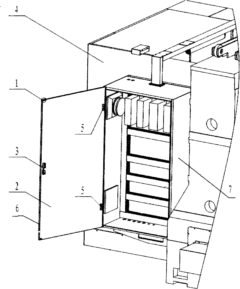
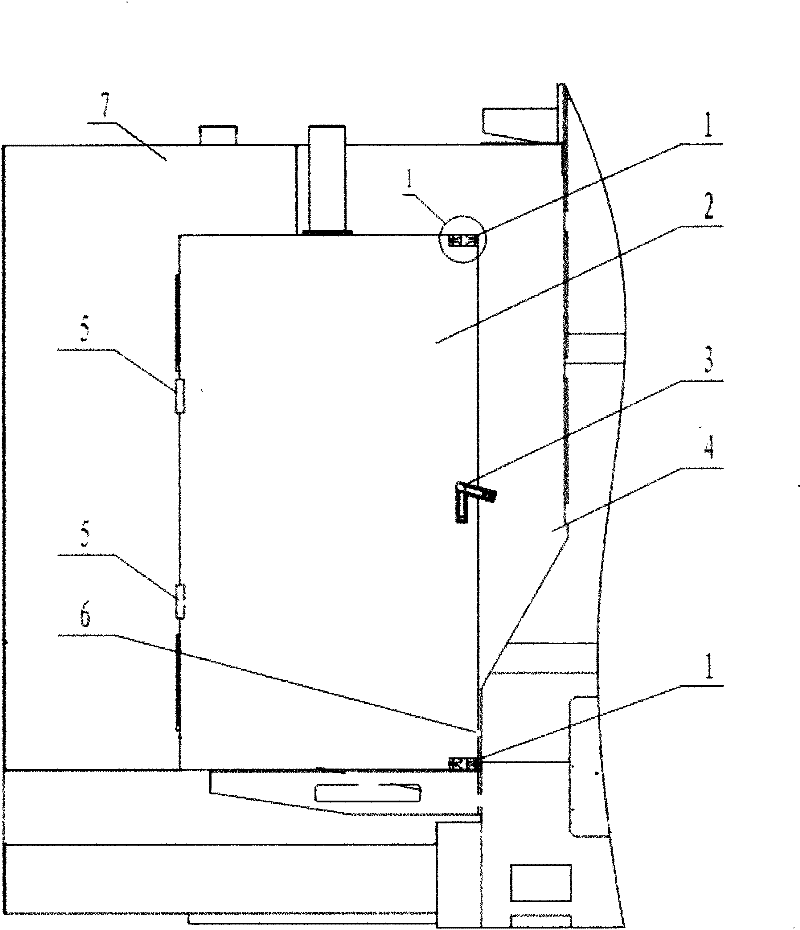
[0023] see figure 1 and figure 2 As shown, the present invention includes a power distribution cabinet box body 7, a power distribution cabinet door 2 and an outer protection 4 of a machining center. The power distribution cabinet door 2 includes a power distribution cabinet right door 6 and a power distribution cabinet left door. Two hinges 5 are arranged on the left door of the power distribution cabinet, and the hinges 5 are fixed with the box body 7 of the power distribution cabinet. The inner positions of the upper and lower ends of the right door side 6 of the power distribution cabinet are respectively provided with permanent magnet shockproof devices 1 . The box body 7 of the power distribution cabinet is fixed on the outer protection 4 of the machining center, forming an organic whole with the machining center.
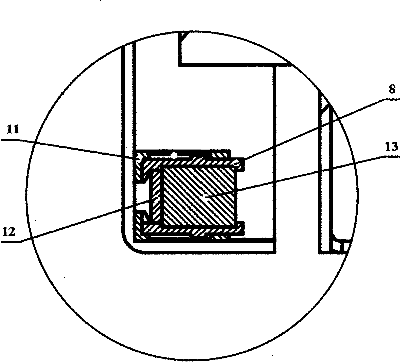
[0024] r...


PUM


Abstract

The invention relates to a cooperation apparatus of a permanent-magnetic door lock of a power distribution cabinet of a machining center. The apparatus comprises a casing of the power distribution cabinet, a door of the power distribution cabinet, and outer protection of the machining center. The door of the power distribution cabinet comprises a right door edge of the power distribution cabinet and a left door edge of the power distribution cabinet; two hinges are arranged on the left door edge of the power distribution cabinet and the hinges are fixed together with the casing of the power distribution cabinet; a safety protection lock is arranged on a middle position of the right door edge of the power distribution cabinet; shockproof devices with permanent magnets are respectively arranged at the upper end and the lower end of the right door edge of the power distribution cabinet. According to the invention, in the aspect of structure design, a spring tongue is arranged for shock absorption, so that pressure and vibration can be effectively alleviated at the moment of suction and disconnection of the permanent magnets, and thus circuits and components in the power distribution cabinet are protected substantially.

Description

technical field [0001] The invention belongs to the field of mechanical manufacturing, and in particular relates to a permanent magnet door lock matching device for a power distribution cabinet of a machining center. Background technique [0002] In the process of designing mechanical protection and installation and use, it was found that due to the increase in the size of the equipment model, the size of the power distribution cabinet supporting the equipment is also gradually increasing. The power distribution cabinet is switched on and off smoothly, and the problem that the door of the power distribution cabinet cannot be closed and opened due to mechanical structure deformation often occurs. At present, most of the economical ordinary electric cabinet locks are equipped with upper, middle and lower mechanical limit methods. It is very high, it is inconvenient to use force up and down at the same time, making the switch more difficult, and there is a vibration effect in ...

Claims


Application Information

Patent Timeline
Patent Type & Authority Applications(China)
IPC IPC(8): H02B1/26E05B65/52
Inventor 王起森仕玉福
Owner QINGDAO HOSEN HEAVY IND
Why Eureka
Try Eureka