Access apparatus of pipeline for anti-back overflow

An access device and anti-overflow technology, which can be used in indoor sanitary piping devices, water supply devices, waterway systems, etc. The effect of secondary pollution

Active Publication Date: 2013-11-27
王凤蕊
View PDF13 Cites 3 Cited by
  • Summary
  • Abstract
  • Description
  • Claims
  • Application Information

AI Technical Summary

Problems solved by technology

[0002] At present, there are many problems in the drainage system, such as leakage, back odor, noise, etc., especially the problems of leakage, pipe blockage, sewage overflowing into the room, and back odor pollution. In order to solve the above problems, many technicians have focused on the above problems Different solutions are proposed: 1. In the special single riser system, a hollow water flow is formed by setting a water channel at the junction of the horizontal pipe and the standpipe, so as to improve the ventilation capacity of the drainage standpipe and reduce the odor return of the floor drain; 2. Adopt Double standpipe method, set up a special ventilation pipe to reduce the problem of floor drain odor return; 3. Adopt double standpipe self-circulation mode to improve the exhaust capacity of the standpipe and reduce the problem of floor drain odor return; 4. In the special long joint single standpipe system, Because the riser pipe is partially expanded, it has a certain impact on interior decoration and occupies indoor space; the above technologies have solved the problem of floor drains to varying degrees, but none of them can solve the problem of blocked sewage overflow

Method used


Image

  • Access apparatus of pipeline for anti-back overflow

Examples


Embodiment 1

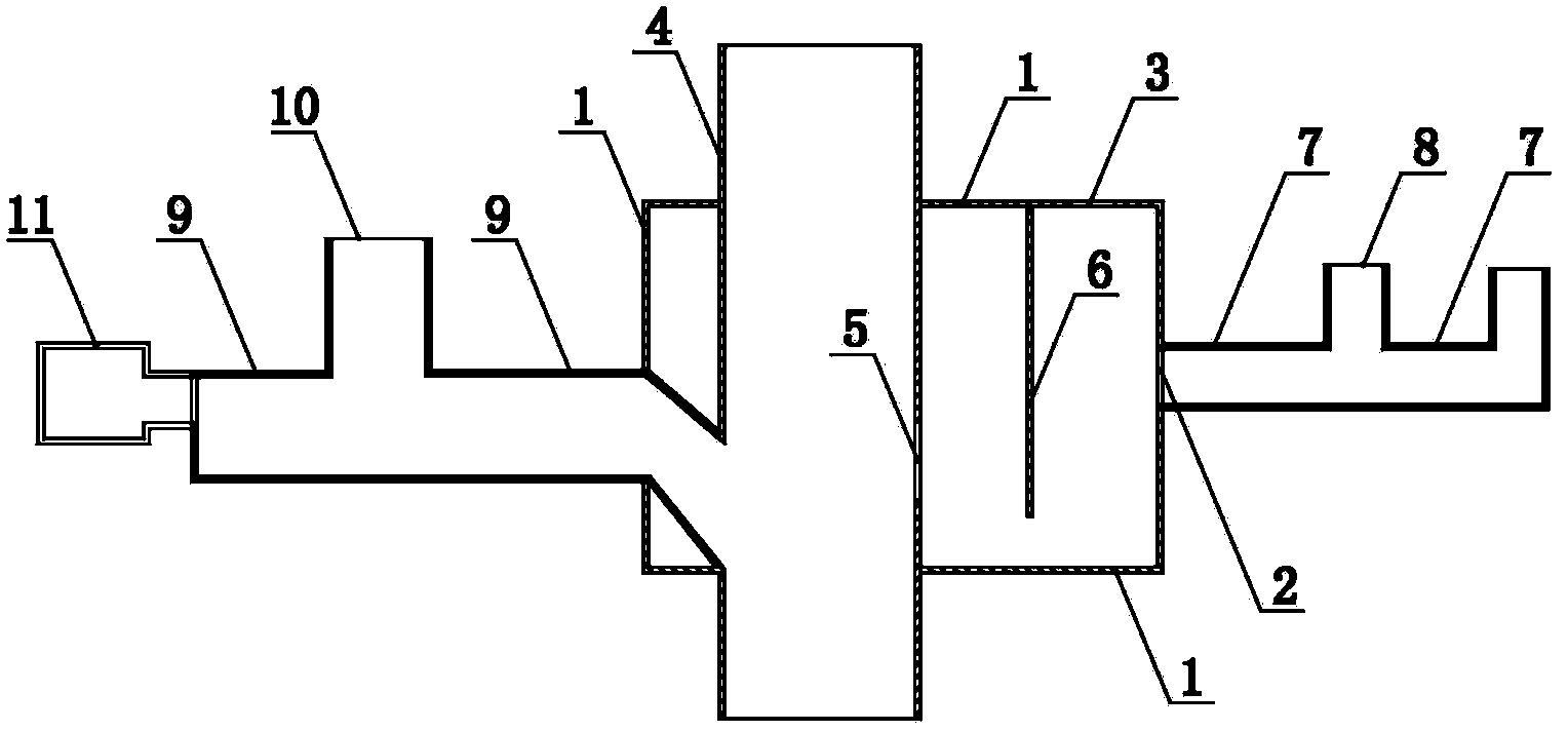
[0021] Such as figure 1 As shown, an anti-backflow pipeline access device includes a riser connecting pipe 4, a sewage drain pipe 9 with a water-sealed sewage discharge port 10, a waste water discharge pipe 7 with a waste water discharge port 8, and an air pressure regulating box 11 , the water-sealed box 1 and the water-sealed dividing hanging plate 6 arranged in the water-sealed box 1, wherein the top of the water-sealed and divided hanging plate 6 is hinged to the inner side of the top box wall of the water-sealed box 1, and the standpipe The connecting pipe 4 is set through the water-sealed box 1, and the standpipe connecting pipe 4 is provided with a drain port 5, and the lowest point of the drain port 5 is not lower than the bottom end of the water-sealed split hanging plate 6 so that The water seal box 1 forms a water seal; when the bottom end of the water seal partition hanging plate 6 is set on the wall of the water seal box 1, the water seal partition hanging plate 6...

Embodiment 2

[0028] The difference between this embodiment and Embodiment 1 is that one end of the sewage drainage pipe passes through the top wall of the water-sealed tank and communicates with the riser connecting pipe, so as to adapt to different drainage methods or structures.

Embodiment 3

[0030] The main difference between this embodiment and Embodiment 1 is that the sewage drainage pipe is arranged above the water-sealed box, that is, one end of the sewage drainage pipe is directly connected with the riser connecting pipe, so as to adapt to different drainage methods or drainage structure.


PUM


Abstract

The invention provides an access apparatus of a pipeline for anti-back overflow. The apparatus which comprises a vertical tube connecting tube, a water seal tank, and a water seal and division hanger plate arranged in the water seal tank is characterized in that: the top of the water seal and division hanger plate is hinged to the inner side of the top tank wall of the water seal tank, the vertical tube connecting tube which is inserted through the water seal tank is provided with a water outlet, and a lowest part of the water outlet is not lower than the bottom of the water seal and division hanger plate; the bottom of the water seal and division hanger plate bears against the wall of the water seal tank, and the water seal and division hanger plate divides the water seal tank into two tanks which are not communicated; and the water outlet is arranged in one of the two tanks, and the wall of the other one of the two tanks is provided with a water inlet. The apparatus of the present invention has the advantages of scientific design, reliable performance, and self seal for anti-back overflow.

Description

technical field [0001] The invention relates to a building water supply and drainage device, in particular to an anti-backflow pipe access device. Background technique [0002] At present, there are many problems in the drainage system, such as leakage, back odor, noise, etc., especially the problems of leakage, pipe blockage, sewage overflowing into the room, and back odor pollution. In order to solve the above problems, many technicians have focused on the above problems Different solutions are proposed: 1. In the special single riser system, a hollow water flow is formed by setting a water channel at the junction of the horizontal pipe and the standpipe, so as to improve the ventilation capacity of the drainage standpipe and reduce the odor return of the floor drain; 2. Adopt Double standpipe method, set up a special ventilation pipe to reduce the problem of floor drain odor return; 3. Adopt double standpipe self-circulation mode to improve the exhaust capacity of the sta...

Claims


Application Information

Patent Timeline
Patent Type & Authority Patents(China)
IPC IPC(8): E03C1/12E03C1/122E03C1/29E03F5/042
Inventor 王凤蕊
Owner 王凤蕊
Why Eureka
Try Eureka