Illuminating system

A lighting system and remote technology, applied in the field of lighting systems, can solve the problems of affecting the luminous efficiency of LED light sources and low luminous efficiency, and achieve the effects of improving luminous efficiency, reducing heat generation, and increasing service life

Inactive Publication Date: 2012-02-22
瑞峰(张家港)光伏科技有限公司
View PDF3 Cites 5 Cited by
  • Summary
  • Abstract
  • Description
  • Claims
  • Application Information

AI Technical Summary

Problems solved by technology

[0005] (3) The luminous efficiency of the LED light source is affected by temperature. When a certain temperature is reached, the higher the temperature of the LED light source, the lower the luminous efficiency. Affect the luminous efficiency of LED light source

Method used


Image

  • Illuminating system
  • Illuminating system

Examples


Embodiment Construction

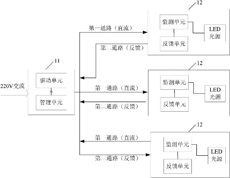
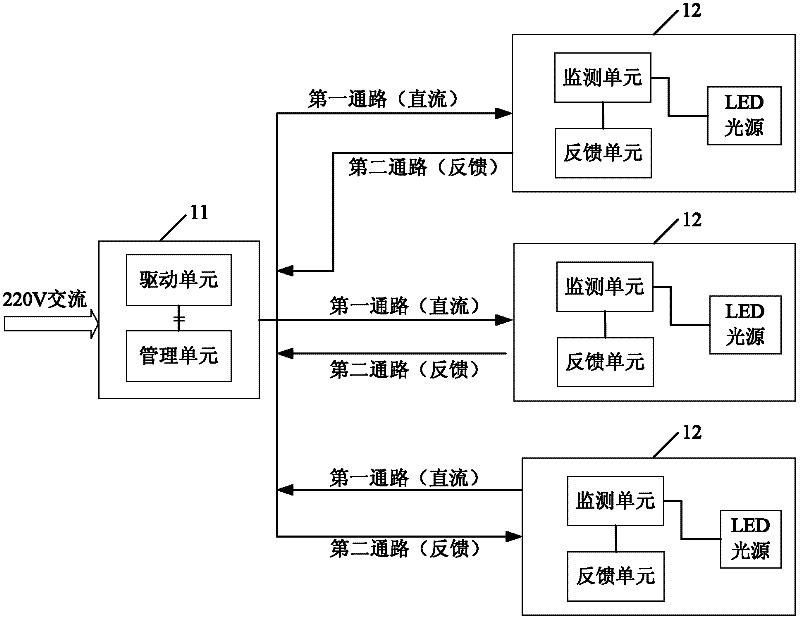
[0034] In the present invention, the control end and the remote end are designed to be separated from each other, and the control end controls the work of the remote end according to the working state parameters collected by the remote end, so that the miniaturization of LED lamps can be realized, the service life of LED lamps can be increased, and the manufacturing cost can be reduced. cost, and at the same time, it can also realize the adjustment of the working state of the remote lighting. Hereinafter, the present invention will be described in detail through specific embodiments in conjunction with the accompanying drawings.

[0035] Please refer to figure 1 , the lighting system according to the embodiment of the present invention includes a control end 11 and a remote end 12 which are separated from each other. The control terminal 11 is responsible for controlling and managing the power supply of the remote terminal. The control terminal 11 includes a drive unit and a...


PUM


Abstract

The invention provides an illuminating system comprising a control end and a far end which are mutually separated, wherein the control end comprises a driving unit and a management unit; the far end comprises an LED (Light-Emitting Diode) light source, a monitoring unit and a feedback unit; the driving unit is used for supplying a direct-current power supply to the LED light source; the monitoring unit is used for obtaining a working state parameter of the LED light source; the feedback unit is used for sending the working state parameter obtained by the monitoring unit to the management unit; and the management unit is used for receiving the working state parameter sent by the feedback unit and controlling the output of the driving unit according to the working state parameter so as to adjust the working state of the LED light source. According to the illuminating system, the miniaturized manufacture of an LED lamp can be realized, the manufacturing cost can be reduced, the service life and luminous efficiency of the LED lamp can be improved, and simultaneously the adjustment of the working state of the far-end illumination also can be realized.

Description

technical field [0001] The invention belongs to the technical field of light emitting diode (LED, Light Emitting Diode) lighting, and particularly relates to a lighting system. Background technique [0002] With the advancement of science and technology, LEDs have been more and more widely used in the field of lighting, and there are more and more designs and improvements around LEDs. In the prior art, an LED lamp usually includes an LED driving circuit and an LED light source (LED light emitting element), and the LED driving circuit and the LED light source are integrated on the same circuit board. It can be seen that the existing LED lamps have an integrated structure, and their LED drive circuit and LED light source are designed as a combined whole, which will cause the following disadvantages: [0003] (1) Since the existing LED lamps include LED drive circuits, the space occupied by the LED drive circuits is relatively large, which is not conducive to the miniaturizati...

Claims


Application Information

Patent Timeline
Patent Type & Authority Applications(China)
IPC IPC(8): H05B37/02F21V23/06F21Y101/02
Inventor 陆磊
Owner 瑞峰(张家港)光伏科技有限公司
Why Eureka
Try Eureka