Light source unit, illumination device, display device, and television receiving device

A light source unit and light source technology, which are applied in the fields of lighting devices, light source units, display devices and television receiving devices, can solve the problems of unevenness, the positional relationship of the diffuser lens of the reflecting member is not fixed, and the instability is not stable.

Inactive Publication Date: 2012-05-23
SHARP KK
View PDF5 Cites 5 Cited by
  • Summary
  • Abstract
  • Description
  • Claims
  • Application Information

AI Technical Summary

Problems solved by technology

[0009] However, when assembling the above-mentioned reflective member to the LED substrate, for example, a method of adhering with double-sided tape or the like is considered, but in this case, when the reflective member is thermally expanded or contracted, the adhesive force may be weak at the unattached portion. Concentrated warping and deflection of parts, resulting in local deformation
In this case, unevenness occurs in the light reflected by the reflection member, and as a result, unevenness may occur in the light emitted from the diffusion lens.
[0010] Therefore, it is considered to abolish the adhesion

Method used


Image

  • Light source unit, illumination device, display device, and television receiving device
  • Light source unit, illumination device, display device, and television receiving device
  • Light source unit, illumination device, display device, and television receiving device

Examples


Embodiment approach 1

[0089] according to Figure 1 to Figure 17 Embodiment 1 of the present invention will be described. In this embodiment, a liquid crystal display device 10 is exemplified. In addition, X-axis, Y-axis, and Z-axis are shown in part of each drawing, and the direction of each axis is described as the direction shown in each drawing. Additionally, the Figure 4 with Figure 5 The upper side shown is the front side, and the lower side in the figure is the back side.

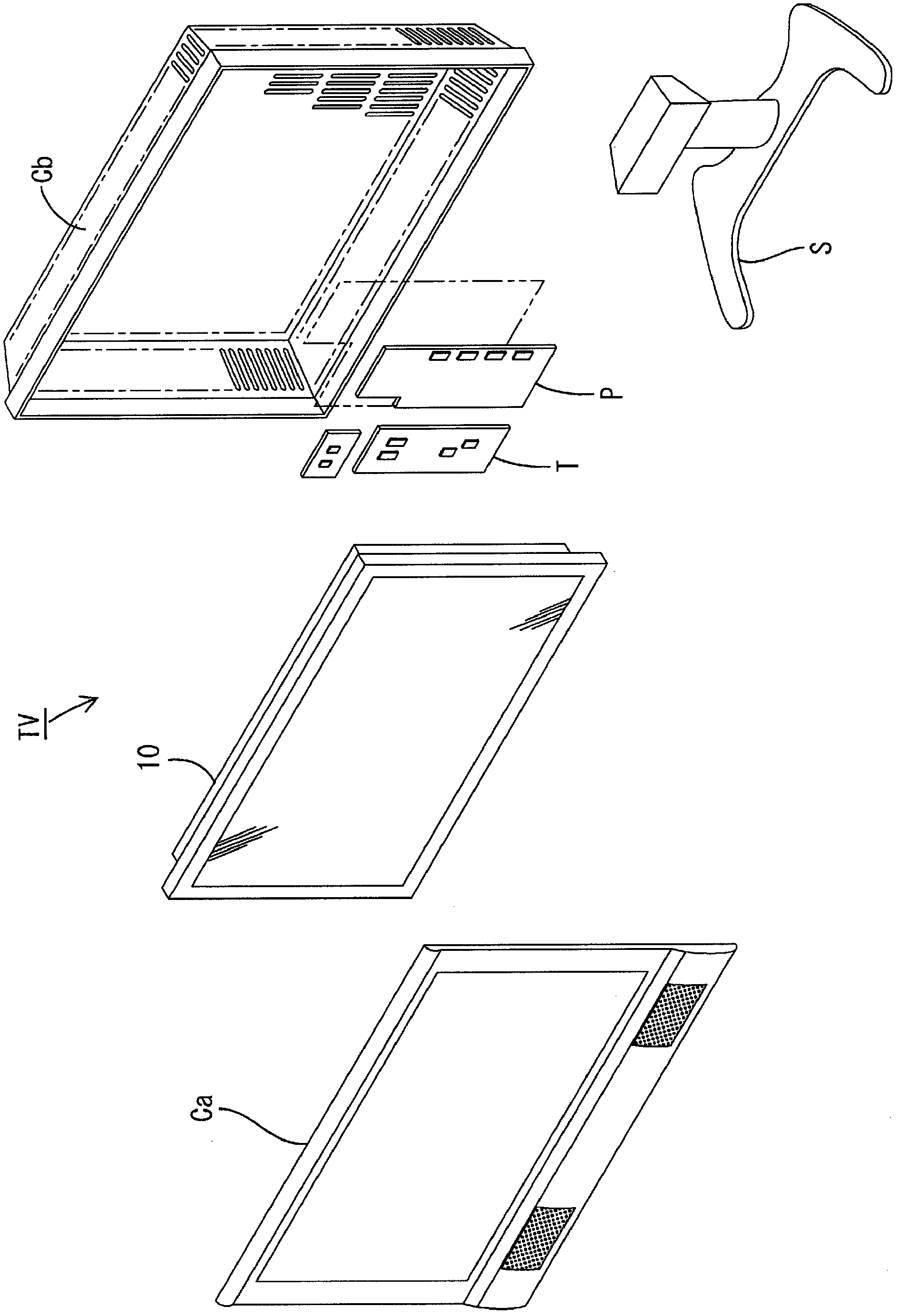
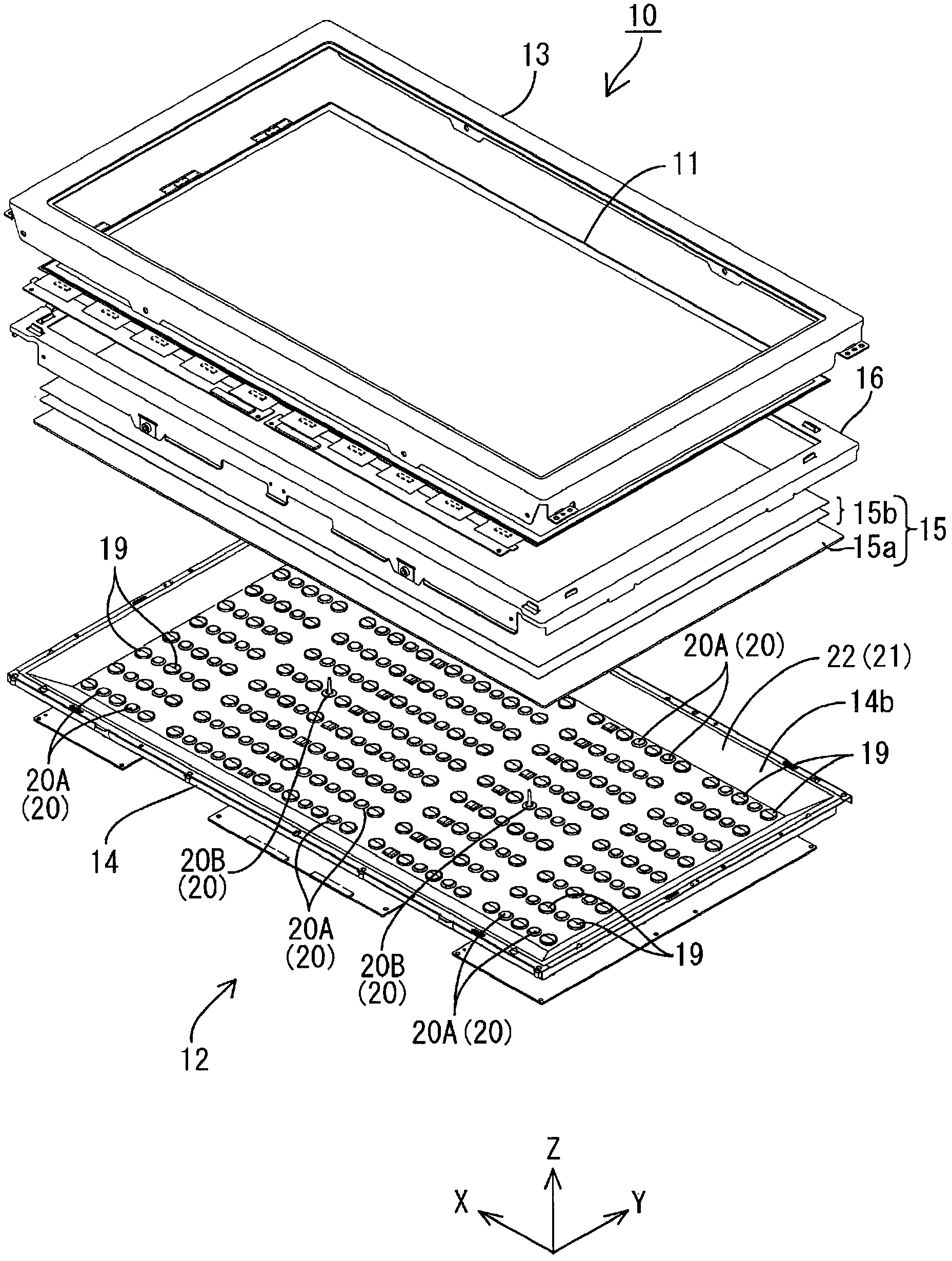
[0090] The television receiver TV of this embodiment is such as figure 1As shown, it comprises a liquid crystal display device 10 , two front and back cases Ca, Cb, a power supply P, a tuner T, and a stand S sandwiching and accommodating the liquid crystal display device 10 . The liquid crystal display device (display device) 10 has a horizontally long square (rectangular) shape as a whole, and is housed in a vertically placed state. The liquid crystal display device 10 such as figure 2 As shown, a liquid cryst...

Embodiment approach 2

[0177] according to Figure 19 or Figure 20 Embodiment 2 of the present invention will be described. In this second embodiment, it is shown that the arrangement and shape of the restricting portion 127 are changed. In addition, redundant descriptions of the same configurations, functions, and effects as those of the first embodiment described above are omitted.

[0178] limit section 127 as Figure 19 with Figure 20 As shown, in the light incident surface 19b of the diffusion lens 19, it is arrange|positioned at the position adjacent to the mounting part 19e, and it is set as the form connected with the mounting part 19e. Specifically, the restricting portion 127 surrounds the base end portion of the mounting portion 19e protruding from the light incident surface 19b, has a substantially annular cross-section, and is connected to the outer peripheral surface of the mounting portion 19e over the entire circumference. In other words, it can be said that in the fitting por...

Embodiment approach 3

[0189] according to Figure 25 Embodiment 3 of the present invention will be described. In this Embodiment 3, it is shown that the restricting portion 227 is provided on the substrate reflection sheet 223 side. In addition, redundant descriptions of the same configurations, functions, and effects as those of the first embodiment described above are omitted.

[0190] Restricted Section 227 AS Figure 25 As shown, it is provided integrally with the reflection sheet 223 for the substrate. Specifically, although the restricting portion 227 is a member different from the substrate reflection sheet 223 , it is integrally adhered to the substrate reflection sheet 223 by a fixing material such as an adhesive. The restricting portion 227 has a substantially block shape, and the surface facing the light incident surface 19b of the diffusion lens 19 is a flat surface parallel to the light incident surface 19b. A gap C2 is left between the restricting portion 227 and the light inciden...


PUM


Abstract

An LED unit U of the present invention includes an LED 17 that is a light source, a diffuser lens 19, a board reflection sheet 23 and a restriction member 27. The diffuser lens 19 is provided to face a light emitting surface 17a of the LED 17. The board reflection sheet 23 is provided to face a surface of the diffuser lens 19 that is closer to the LED 17 and is configured to reflect light. The restriction member 27 projects from the diffuser lens 19 toward the board reflection sheet 23 and restricts positional relationship between the diffuser lens 19 and the board reflection sheet 23.

Description

technical field [0001] The present invention relates to a light source unit, an illuminating device, a display device and a television receiving device. Background technique [0002] For example, a liquid crystal panel used in a liquid crystal display device such as a liquid crystal television does not emit light by itself, and therefore requires a backlight device as an additional lighting device. This backlight device is provided with: base, it is arranged on the rear side (opposite side with display surface) of liquid crystal panel, and the surface opening of side of liquid crystal panel; Light source, it is accommodated in the base; It is arranged in the opening of the base and is used to effectively release the light emitted by the light source to the side of the liquid crystal panel. [0003] Among the components of the above-mentioned backlight device, for example, LEDs may be used as light sources. In this case, an LED board on which the LEDs are mounted is housed i...

Claims


Application Information

Patent Timeline
IPC IPC(8): F21S2/00F21V5/00F21V5/04G02F1/13357F21Y101/02
CPCG02B19/0061G02B27/0916G02B19/0028
Inventor 横田匡史
Owner SHARP KK
Why Eureka
Try Eureka