Filter device

A filter device and filter surface technology, applied in the direction of filtration separation, membrane filter, fixed filter element filter, etc., can solve the problems of high manufacturing cost and operation cost, expensive structure, complicated system, etc., and achieve low-cost manufacturing, Low structural outlay, comfortable and simple replacement process

Inactive Publication Date: 2012-09-12
HYDAC PROCESS TECH
View PDF7 Cites 6 Cited by
  • Summary
  • Abstract
  • Description
  • Claims
  • Application Information

AI Technical Summary

Problems solved by technology

Conventional filter devices for this use are therefore structurally complex in construction
This leads to a consi

Method used


Image

  • Filter device
  • Filter device
  • Filter device

Examples


Embodiment Construction

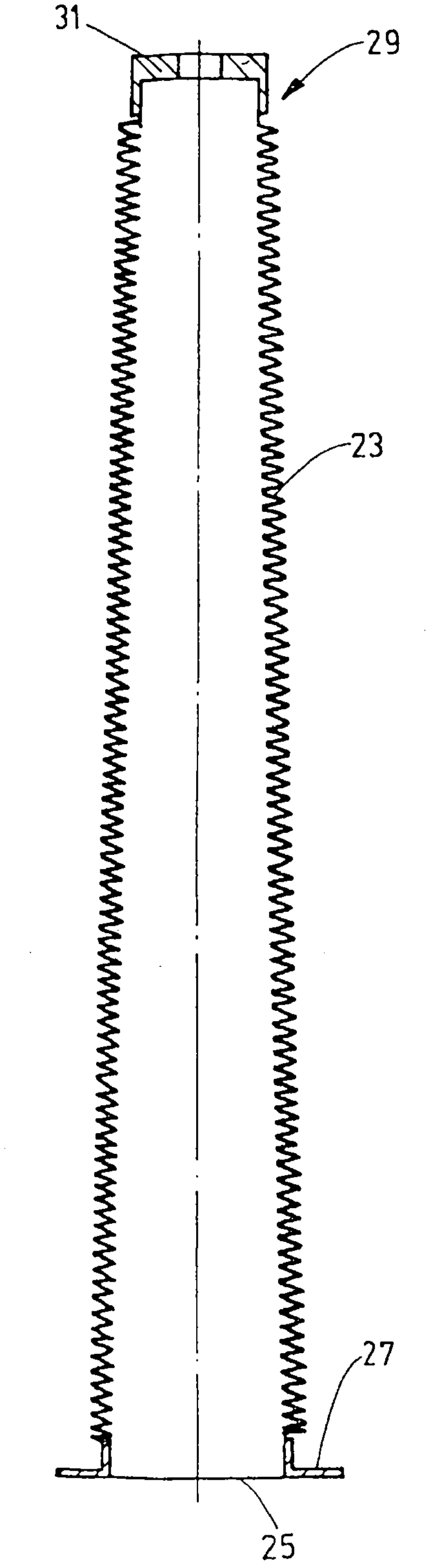
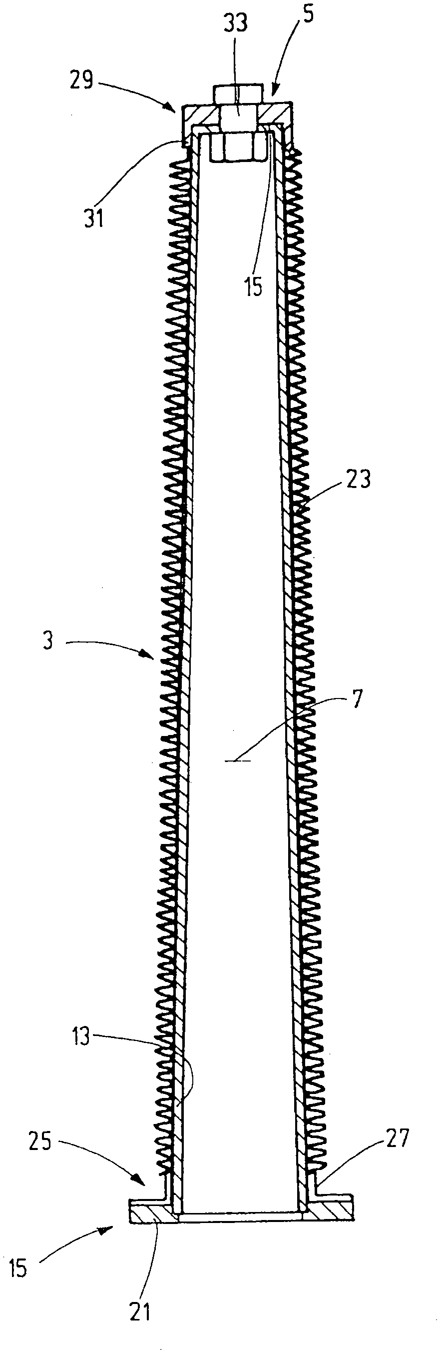
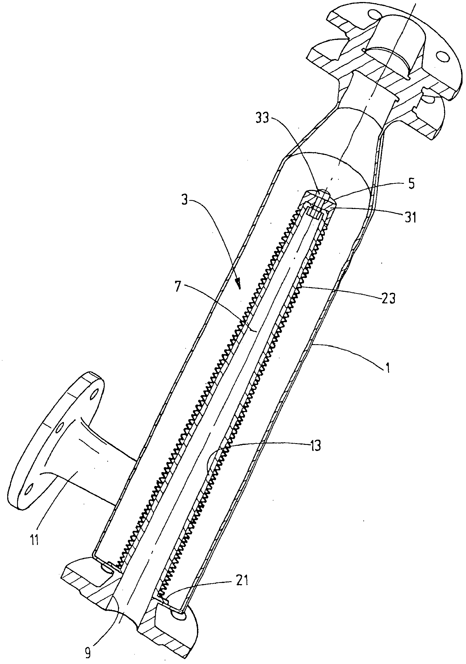
[0027] First of all, with the help of Figures 1 to 5 The example of the filtering device illustrates the present invention, wherein, in Figure 4 In the filter housing designated by 1 is arranged a filter element designated as a whole by 3 which is designed in the type of a so-called filter candle stick and forms two filter stages in operation. In this example, the filter element 3 has a shape that tapers slightly conically towards the closed end 5 . However, the invention can also be implemented as a cylindrically shaped filter element. as in Figure 4 , the filter element 3 is arranged in the housing 1 in such a way that the inner filter cavity 7 adjoins the housing bore 9 which is arranged at one axial end of the filter housing 1 And an inflow hole is formed during the filtering operation. The lateral housing connection 11 forms an outlet for the cleaned medium during filtering operation. Further details of the embodiment to be explained here of the filter element 3 c...


PUM


Abstract

The invention relates to a filter device, in particular for fluids such as hydraulic oil, lubricating media, processing, surface or sea water, having at least one filter element (3) that has at least one effective filter surface (23), which is suitable for removing contaminants from a media flow crossing the filter surface, wherein an effective filter surface is designed as a flexible filter sock (23) that can be pulled onto a support body (13) of the filter element (3). The invention is characterized in that the filter sock (23), while enlarging the effective filter surface thereof, is designed to be longer in the axial direction of the filter element (3) such that the effective filter surface lies in folds upon pulling the filter sock (23) over the support body (13).

Description

technical field [0001] The invention relates to a filter device, in particular for fluids such as hydraulic oil, lubricating medium, process water, surface water or sea water, which filter device has at least one filter element with at least one effective filter surface, The active filter surface is suitable for absorbing pollutants from a medium flow passing through it, wherein the active filter surface is provided in the form of a filter bag which can be slipped onto the carrier of the filter element. Background technique [0002] In systems and machines in which flowable media are used as operating media, the operational safety depends to a large extent on the perfect properties of the media in question. Therefore, especially in high-value installations, that is to say for economic reasons, it is necessary to provide suitable filters for the media involved as gaseous media or fluids in order to remove contamination that occurs during operation. Particular demands are pla...

Claims


Application Information

Patent Timeline
IPC IPC(8): B01D29/11
CPCB01D29/111B01D29/21B01D29/232B01D29/48B01D29/52B01D29/58B01D29/66B01D29/70B01D29/908B01D2201/02B01D39/00
Inventor R·弗努克M·温特
Owner HYDAC PROCESS TECH
Why Eureka
Try Eureka