Hole plate mixed spiral flow pipeline energy dissipating device

A technology of mixing screw and energy dissipation device, applied in the direction of pipe elements, pipes/pipe joints/pipe fittings, mechanical equipment, etc., can solve the problems of affecting water flow, small adjustment range, inconvenient operation, etc., to increase the adjustment range, adjust The effect of large range and convenient operation

Inactive Publication Date: 2012-10-03
TAIYUAN UNIV OF TECH
View PDF5 Cites 12 Cited by
  • Summary
  • Abstract
  • Description
  • Claims
  • Application Information

AI Technical Summary

Problems solved by technology

[0006] The present invention is an orifice mixed spiral flow pipeline energy dissipation device, which aims at overcoming the disadvantages of existing pipeline energy dissipation devices such as high cost, inconvenient operation, influence on water delivery flow, small adjustment range, and pipeline vibration during the energy dissipation process, thereby Provide a technical solution for a screen-type orifice plate mixed spiral flow energy dissipation device

Method used


Image

  • Hole plate mixed spiral flow pipeline energy dissipating device
  • Hole plate mixed spiral flow pipeline energy dissipating device
  • Hole plate mixed spiral flow pipeline energy dissipating device

Examples


Embodiment approach 1

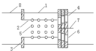
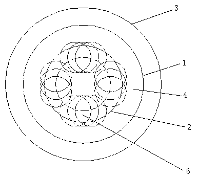
[0023] Implementation mode 1: Such as figure 1 As shown, in the water pipeline, the outer pipe 1, the inner pipe 2 and the water delivery branch pipe 8 are connected through the flange 3, and the outer pipe 1, the inner pipe 2 and the water delivery branch pipe 8 are kept concentric, and the diameter of the outer pipe 1 is the same as that of the water delivery pipe The branch pipes 8 are the same, and the oblique round holes 5 are arranged symmetrically and evenly at a certain inclination angle around the inner pipe 2 like a screen. If the ratio of the total area of ​​the oblique circular holes 5 to the cross-sectional area of ​​the outer pipe 1 is 80%, each orifice 4 is connected by a rotating shaft 7, and the rotating shaft 7 coincides with the central axis of the water delivery branch pipe 8, and each orifice 4 Along the axial direction of the water delivery branch pipe 8, the perfect circular holes 6 are arranged like a screen, and the ratio of the total area of ​​the ...

Embodiment approach 2

[0025] Implementation mode 2: Such as figure 1 As shown, in the water pipeline, the outer pipe 1, the inner pipe 2 and the water delivery branch pipe 8 are connected through the flange 3, and the outer pipe 1, the inner pipe 2 and the water delivery branch pipe 8 are kept concentric, and the diameter of the outer pipe 1 is the same as that of the water delivery pipe The branch pipes 8 are the same, and the oblique square holes 5 are symmetrically and evenly arranged around the inner pipe 2 like a screen according to a certain inclination angle. Assuming that the ratio of the total area of ​​the oblique square hole 5 to the cross-sectional area of ​​the outer pipe 1 is 45%, each orifice plate 4 is connected by a rotating shaft 7, and the rotating shaft 7 coincides with the central axis of the water delivery branch pipe 8, and each orifice plate 4 Along the axial direction of the water delivery branch pipe 8, the square holes 6 are arranged like a screen, and the ratio of the...

Embodiment approach 3

[0027] Implementation mode 3: Such as figure 1As shown, in the water pipeline, the outer pipe 1, the inner pipe 2 and the water delivery branch pipe 8 are connected through the flange 3, and the outer pipe 1, the inner pipe 2 and the water delivery branch pipe 8 are kept concentric, and the diameter of the outer pipe 1 is the same as that of the water delivery pipe The branch pipe 8 is the same, and the oblique spiral holes 5 are arranged symmetrically and evenly at a certain inclination angle around the inner pipe 2 like a screen. Assuming that the ratio of the total area of ​​the oblique spiral holes 5 to the cross-sectional area of ​​the outer pipe 1 is 10%, the positive spiral holes 6 are arranged on the orifice plate 4 along the axial direction of the water delivery branch pipe 8 like a screen, and the positive spiral holes 6 are arranged on the orifice plate 4. The ratio of the total area of ​​the holes 6 to the cross-sectional area of ​​the outer tube 1 is 10%. The ...


PUM


Abstract

The invention relates to a hole plate mixed spiral flow pipeline energy dissipating device which belongs to the technical field of pipeline water transmission and is characterized in that the hole plate mixed spiral flow pipeline energy dissipating device is in a screen mesh type. The hole plate mixed spiral flow pipeline energy dissipating device consists of an outer pipe 1, an inner pipe 2, a flange 3, a hole plate 4, inclined holes 5, non-inclined holes 6 and a rotating shaft 7, wherein the outer pipe 1 is concentrically connected with the inner pipe 2 through the flange 3, the inclined holes 5 are symmetrically and uniformly formed around the inner pipe 2 in accordance with inclination angles, the inner pipe 2 is connected with the first hole plate 4, the hole plates 4 are connected through the rotating shaft 7 which coincides with the central axis of the outer pipe 1, and each non-inclined hole 6 is formed on each hole plate 4 in the axis direction. According to the hole plate mixed spiral flow pipeline energy dissipating device, the adjusting range of pipeline energy dissipation is greatly increased in a condition that the water transmission flow is not affected, so that the axial and circumferential force balance of the energy dissipating device is realized, the defect of pipe vibration in the process of energy dissipation is completely overcome, the safety and stability of a water transmission system are guaranteed, and the service life is prolonged.

Description

technical field [0001] The invention relates to an orifice plate mixed spiral flow pipeline energy dissipation device, which belongs to the technical field of pipeline water delivery, relates to an energy dissipation device in a pipeline water delivery system, in particular to a screen type orifice plate mixed spiral flow pipeline energy dissipation device technical solutions. Background technique [0002] In pipeline water transportation, the pressure in the pipeline is a necessary condition for the energy of the fluid to be transported, but in some cases, due to the topography and other conditions of the pipeline system, the pressure head of some pipeline sections or under certain conditions often exceeds the pressure head of the fluid to be transported. The consumed energy, if this part of the remaining energy is not eliminated, will increase the investment in the pipeline system and cause harm to the pipeline system facilities and downstream buildings. [0003] Pipeline...

Claims


Application Information

Patent Timeline
Patent Type & Authority Applications(China)
IPC IPC(8): F16L55/02
Inventor 李永业李飞童学卫王锐孙西欢马娟娟
Owner TAIYUAN UNIV OF TECH
Why Eureka
Try Eureka