
Cascade dynamic nitrogen adsorption instrument
A nitrogen adsorption and dynamic technology, applied in the direction of instruments, scientific instruments, measuring devices, etc., can solve the problems of inability to adapt to fast and real-time detection requirements, complex and difficult design and implementation, and decreased test efficiency, and improve the test efficiency. , The effect of simple design and convenient operation
- Summary
- Abstract
- Description
- Claims
- Application Information
AI Technical Summary
Problems solved by technology
Method used
Image

Examples
Embodiment Construction
[0015] The invention adopts a four-way electromagnetic valve, cleverly controls the gas path flow circuit, and realizes fast and reliable testing that only changes the gas path flow and always keeps the sample tube in the liquid nitrogen cup.
[0016] The technical solutions of the present invention will be described in further detail below in conjunction with the accompanying drawings and embodiments.
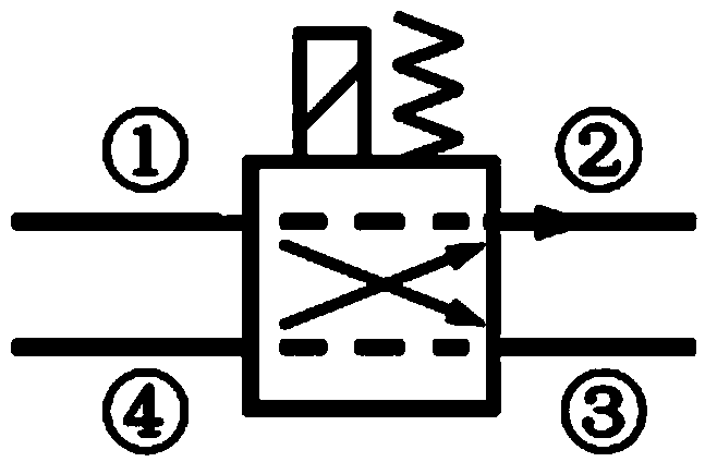
[0017] see figure 1 , that is, the schematic diagram of the solenoid valve. The initial state of the solenoid valve (shown by the dotted line): ① and ② are conducting, ③ and ④ are conducting; (nitrogen partial pressure adjustment state); the solenoid valve is energized and the state changes (shown by the solid line): ① and ③ are conducting ② and ④ are turned on. (Nitrogen adsorption test status)
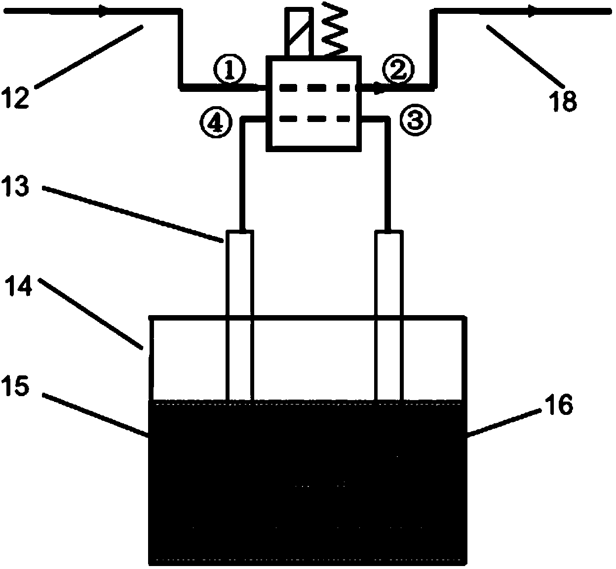
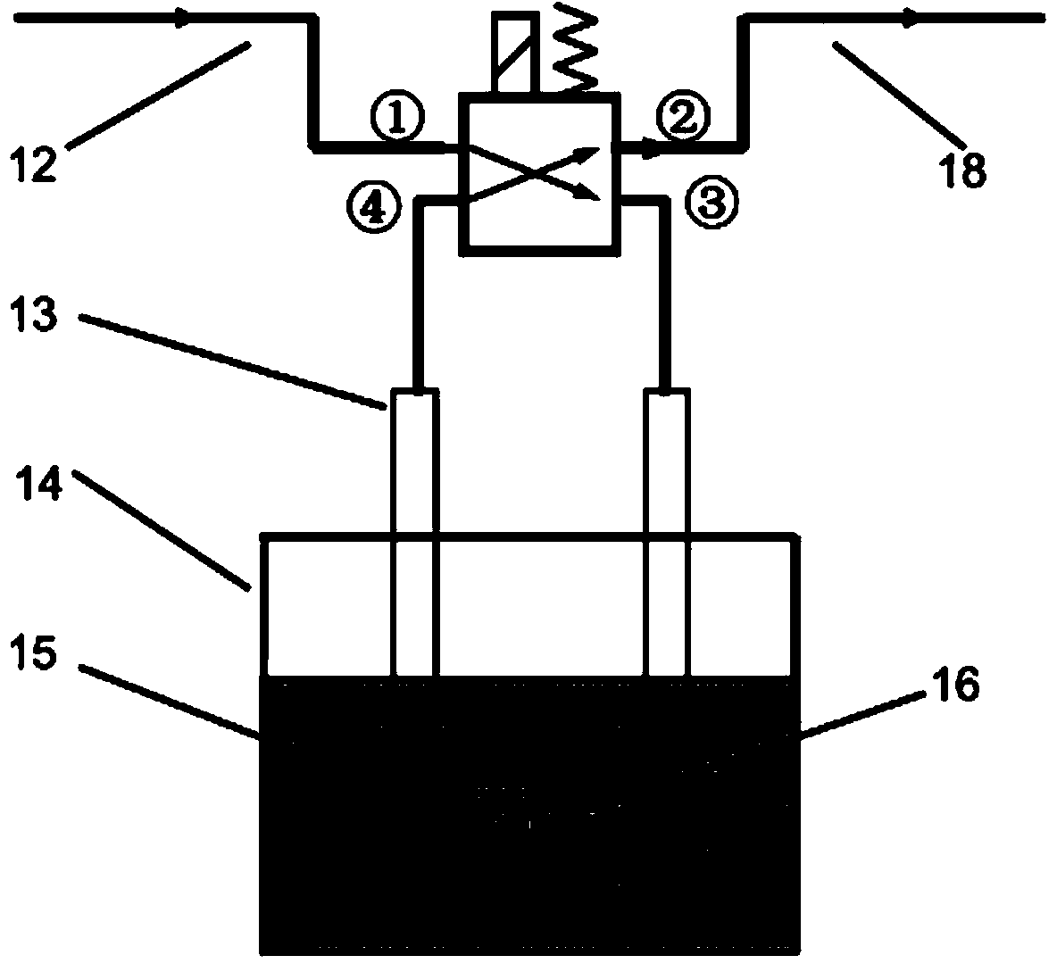
[0018] see figure 2 , figure 2 is a schematic diagram of the nitrogen partial pressure regulation state. The air inlet 12 is directly derived from the 18 air outlets by ① and...
PUM
 Abstract
Description
Claims
Application Information