Spectacle frame capable of rapidly adjusting horizontal position

A mirror frame and optical platform technology, applied in the field of mirror frames, can solve the problems of small adjustment margin, troublesome operation, time-consuming and laborious, etc., and achieve the effect of simple mechanical structure and good adjustment effect

Inactive Publication Date: 2012-11-28
BEIJING GK LASER TECH
View PDF5 Cites 4 Cited by
  • Summary
  • Abstract
  • Description
  • Claims
  • Application Information

AI Technical Summary

Problems solved by technology

The disadvantage of this kind of mirror frame fixed on the breadboard is that the adjustment margin is small. Only rely on the margin of the screw hole on the base of the mirror frame for adjustment, and can only make small movements on the optical bre

Method used


Image

  • Spectacle frame capable of rapidly adjusting horizontal position
  • Spectacle frame capable of rapidly adjusting horizontal position
  • Spectacle frame capable of rapidly adjusting horizontal position

Examples


Example Embodiment

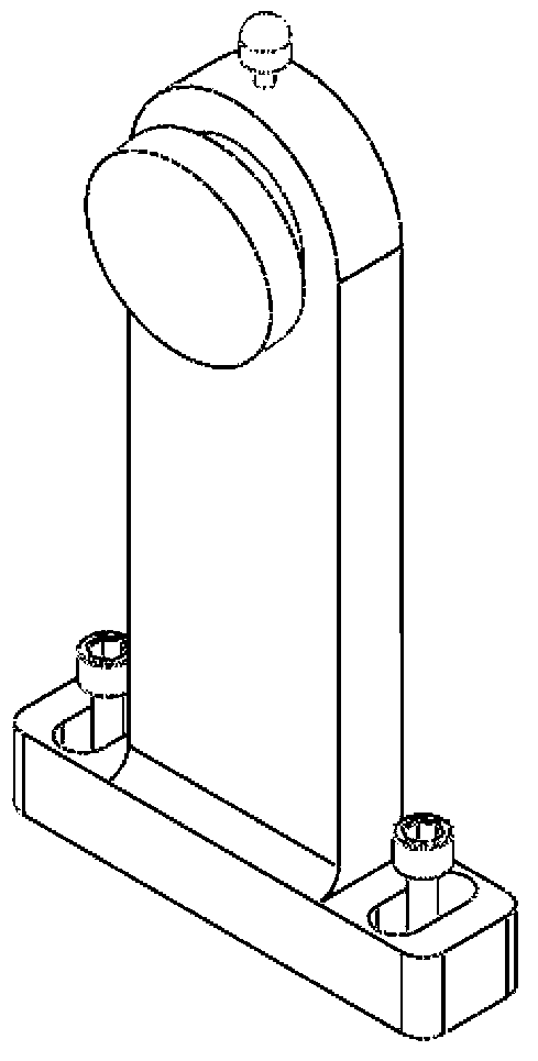
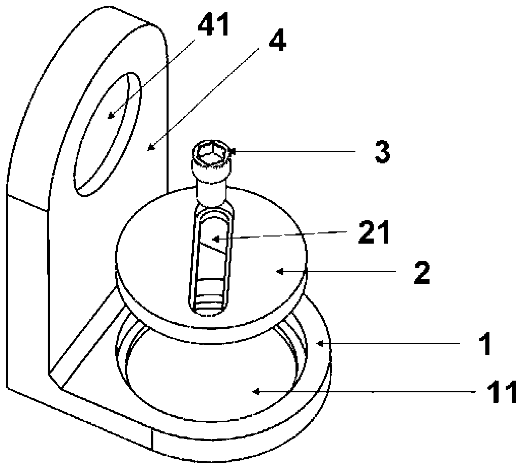
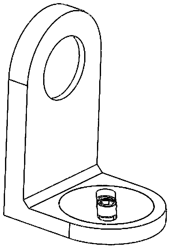
[0022] This embodiment provides a spectacle frame with a structure such as figure 2 Shown, including:

[0023] The frame body 4 has a frame hole 41 for accommodating optical elements;

[0024] The base 1, which is vertical and connected to the main body of the frame, is used to contact the optical table. It has a through hole 11. The side wall of the through hole is stepped. The diameter of the side where the through hole 11 contacts the optical table is relatively small. The caliber on one side is relatively large;

[0025] The circular adapter plate 2 is placed in the above-mentioned through hole 11, and has a diameter larger than the diameter of the side of the through hole 11 that is in contact with the optical table, so that the adapter plate is stuck and prevents the adapter plate from being directly connected to the optical table. Contact, the middle area of ​​the adapter plate has a long through slot 21, the screw 3 can be installed in the slot 21, and the top diameter of t...


PUM


Abstract

The invention provides a spectacle frame. The spectacle frame comprises a spectacle frame main body, a base and a circular changeover panel, wherein the spectacle frame main body is used for bearing an optical element; the base is connected with the spectacle frame main body, in contact with an optical platform and provided with a through hole; the circular changeover panel is placed in the through hole and can rotate in the through hole; a long strip-shaped through slot is formed in the changeover panel; and through the adoption of the slot, the changeover panel and the base are relatively fixed by a fixing device and the changeover panel and the base are both fixed on the optical platform.

Description

technical field [0001] The invention relates to a mirror frame, in particular to a mirror frame whose horizontal position can be adjusted. Background technique [0002] In the process of laser processing, the basic structure of the traditional mirror frame is as follows: figure 1 Secured to the optics breadboard by means of two screws on the base of the frame as shown. The disadvantage of this kind of mirror frame fixed on the breadboard is that the adjustment margin is small, and only rely on the margin of the screw hole on the base of the mirror frame for adjustment, and can only make small movements on the optical breadboard. When the mirror frame needs to be enlarged When the size is moved, the screws on the base of the mirror frame must be completely loosened, removed, and re-fixed in a new hole on the breadboard. The operation is cumbersome and time-consuming. Contents of the invention [0003] Therefore, the purpose of the present invention is to provide a mirror ...

Claims


Application Information

Patent Timeline
IPC IPC(8): H01S3/02
Inventor 邱基斯樊仲维唐熊忻
Owner BEIJING GK LASER TECH
Why Eureka
Try Eureka