Oil saving accelerator

A speed booster and diaphragm technology, which is applied in the direction of machines/engines, secondary air defueling, engine components, etc., can solve problems such as poor sealing effect and poor air intake, so as to reduce fuel consumption, reduce exhaust emissions, and increase torque Effect

Inactive Publication Date: 2013-03-27
浙江宇嘉新能源科技股份有限公司
View PDF6 Cites 19 Cited by
  • Summary
  • Abstract
  • Description
  • Claims
  • Application Information

AI Technical Summary

Problems solved by technology

[0008] The present invention needs to overcome the disadvantages of poor sealing effect and poor air intake in the prior art, and the present invention provides a fuel-saving speed booster with good sealing effect and accelerated air inflow

Method used


Image

  • Oil saving accelerator
  • Oil saving accelerator
  • Oil saving accelerator

Examples


Embodiment Construction

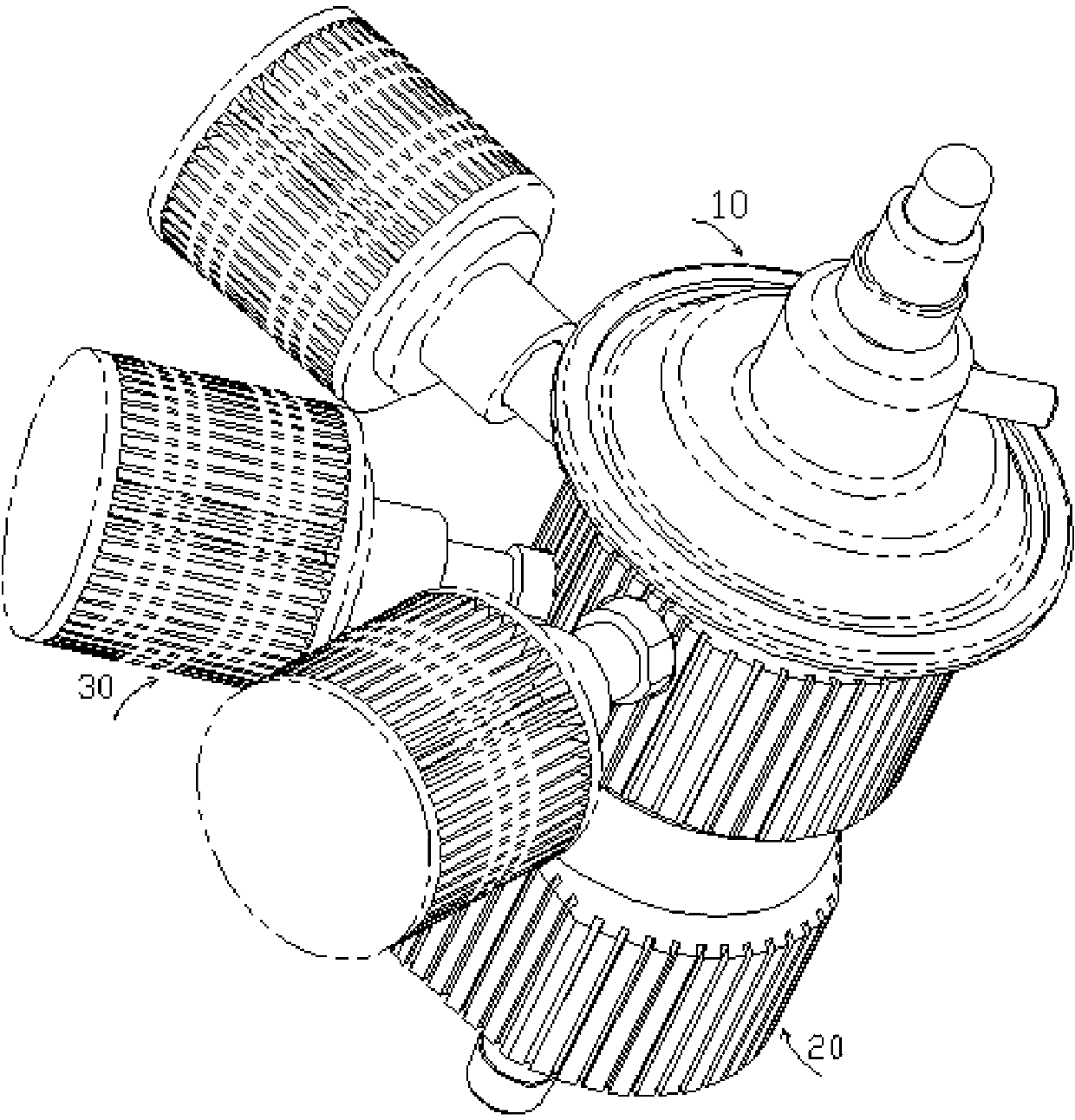
[0036] Refer to attached picture

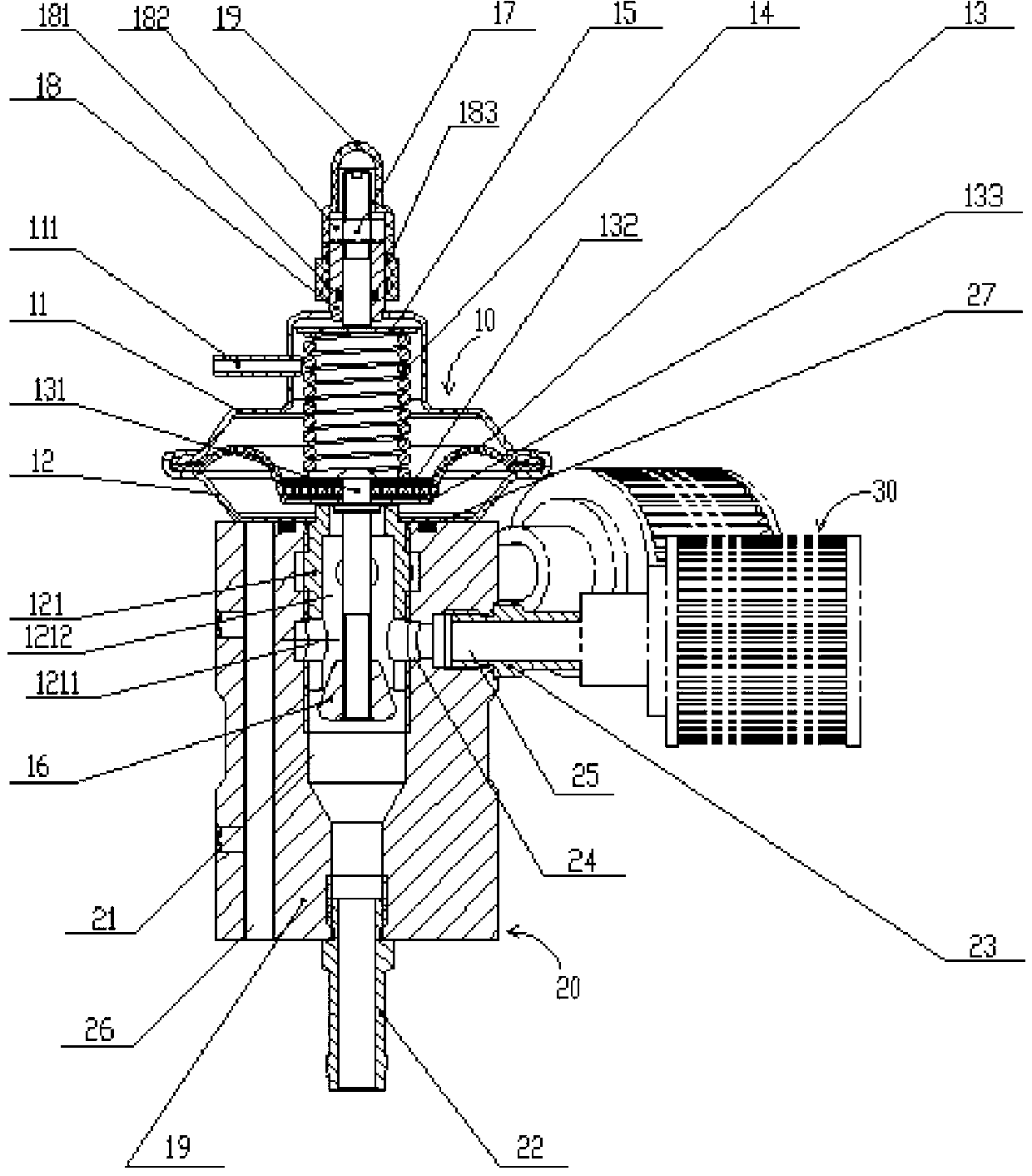
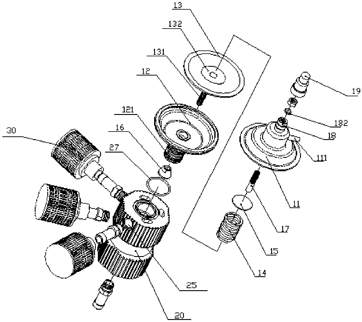
[0037] The secondary speed-increasing lifting fuel economizer according to the present invention is characterized in that it includes:

[0038] A vacuum diaphragm seat, including the first diaphragm seat 11, the second diaphragm seat 12 that are sealed together, and the diaphragm 13 clamped between the first diaphragm seat 11 and the second diaphragm seat 12;

[0039] The first diaphragm seat 11 has a first screw rod 17 at one end away from the second diaphragm seat 12, and the part of the screw hole in the first screw rod 17 adjacent to the first diaphragm seat 11 is a straight hole portion with a smooth inner wall; A control pipe 111 on a diaphragm seat 11 makes the inner cavity of the first diaphragm seat communicate with the engine air circuit;

[0040] One end of the second diaphragm seat 12 away from the first diaphragm seat 11 is provided with a second screw rod 121, the second screw rod 121 has an external thread, and its center is p...


PUM


Abstract

The invention discloses an oil saving accelerator. The oil saving accelerator comprises a vacuum diaphragm seat and a fixed seat with two ends, wherein the vacuum diaphragm seat comprises a first diaphragm seat and a second diaphragm seat which are sealed in a butt jointing way as well as a diaphragm clamped between the first diaphragm seat and the second diaphragm seat; the center of the fixed seat is provided with a first through hole running through the two ends of the fixed seat, one end of the first through hole is in screw connection with a first screw rod of the second diaphragm seat, while the other end of the first through hole is connected with a pipe joint; the wall surface of the fixed seat, adjacent to a second screw rod, is provided with a plurality of air vents for connecting an air cleaner; the inner wall surface of the first through hole is provided with an annular groove; the inner end openings of the air vents are positioned inside the annular groove; and a second through hole is communicated with the annular groove.

Description

technical field [0001] The invention relates to a fuel-saving speed-increasing device for an automobile engine, which is related to the torque when the vehicle engine enters an acceleration state from an idle state. technical background [0002] The supplementary path of the fresh air of the car generator is: from the air filter through the intake manifold, and enter the combustion chamber of the engine with an appropriate oil-air mixing ratio. As the car accelerates from idle, the driver applies more gas, allowing more fuel to enter the engine. However, at this time, the amount of air entering the generator combustion chamber from the intake manifold cannot be increased instantaneously. As a result, the oil-gas mixture ratio is out of balance, and the fuel consumption increases. [0003] The moment the car engine starts or accelerates, the engine's demand for fresh air increases instantly, but the conventional car engine air supply system cannot do this. China Taiwan Pat...

Claims


Application Information

Patent Timeline
Patent Type & Authority Applications(China)
IPC IPC(8): F02M23/04
Inventor 郭清明
Owner 浙江宇嘉新能源科技股份有限公司
Why Eureka
Try Eureka