air blower

A technology of air blowing and air, which is applied in the direction of pump devices, pipeline layout, and components of pumping devices for elastic fluids. diffuse effect

Active Publication Date: 2016-01-06
KIMURA KOHKI CO LTD
View PDF12 Cites 0 Cited by
  • Summary
  • Abstract
  • Description
  • Claims
  • Application Information

AI Technical Summary

Problems solved by technology

If the above-mentioned air blowing device is used in the air conditioning system, the air supplied to the air-conditioned space is low in temperature and the air volume is small, so that the air flow cannot be diffused, causing problems of cold draft or condensation

Method used


Image

  • air blower
  • air blower
  • air blower

Examples


Embodiment Construction

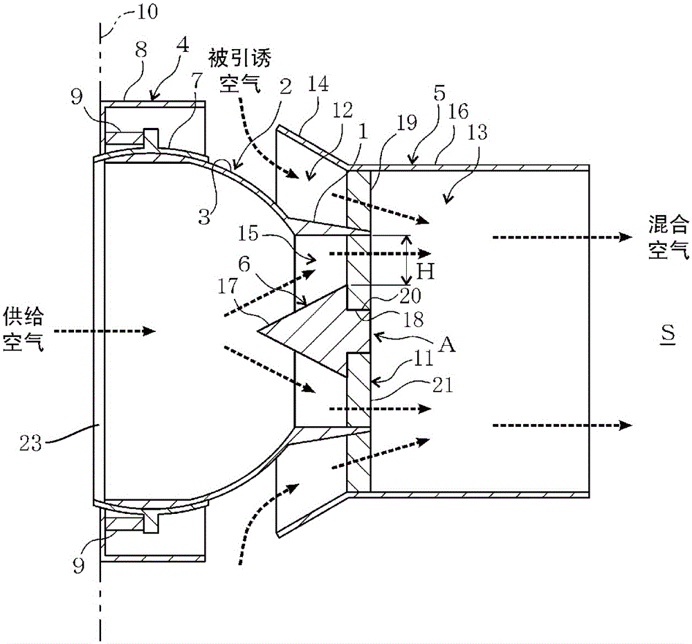
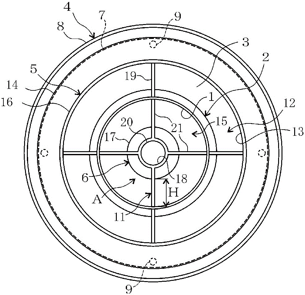
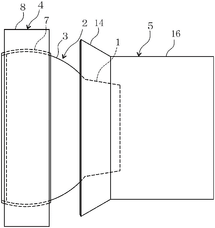
[0030] Figure 1 ~ Figure 4 An example of the air blowing device of the present invention is shown. This air blowing device includes an outlet body 2 , an outer package 4 and an outer cylinder 5 . The blower outlet body 2 has a suction port 23 and a nozzle-shaped blower port 1 , and blows air fed in from the suction port 23 into the air-conditioned space S from the blower port 1 as supply air. The outlet main body 2 has a spherical portion 3 having a spherical outer surface, an air inlet portion 23 is provided at a base end portion of the spherical portion 3 , and an outlet portion 1 is provided at a distal end portion of the spherical portion 3 . The outer package 4 holds the outlet main body 2 in a movable manner so that the blowing direction of the supply air can be changed. The outer package 4 rotatably holds the spherical portion 3 of the outlet main body 2 from the outside. Therefore, the spherical part 3 can rotate freely with respect to the outer package 4, and can ...


PUM


Abstract

The present invention relates to an air blowing device with both comfort and energy saving, comprising: a suction port and a nozzle-shaped blower port, and blows the air sent in from the suction port as supply air from the blower port to the air-conditioned space The main body of the blowing outlet; the outer package that movably holds the main body of the blowing outlet so that the blowing direction of the supplied air can be changed; The outer cylinder is arranged in front of the outlet than the outlet; the base end of the outer cylinder and the main body of the outlet form an annular induction air path that introduces the air in the air-conditioned space S into the interior of the outer cylinder as induced air. , the inside of the outer cylinder portion located in front of the air outlet portion forms a mixed air blowing air path communicating with the air outlet portion and the induced air path.

Description

technical field [0001] The present invention relates to an air blowing device. Background technique [0002] The air blowing device has a spherical portion having a spherical outer surface and a nozzle-shaped outlet portion, and the blowing direction of air blown from the outlet portion is changed by rotating the spherical portion supported by the supporting member. [0003] Prior art literature: [0004] Patent Document 1: Japanese Patent Application Laid-Open No. 8-200785. Contents of the invention [0005] Problems to be solved by the invention: [0006] Furthermore, for the purpose of saving energy for generating blowing power, there is an air-conditioning system that supplies supply air of lower temperature and less air volume than usual from an air conditioner to a space to be conditioned, such as a room. If the above-mentioned air blowing device is used in the air conditioning system, the air supplied to the air-conditioned space is low temperature and the air vo...

Claims


Application Information

Patent Timeline
Patent Type & Authority Patents(China)
IPC IPC(8): F24F13/06
CPCF04D25/14F04D29/403F05D2210/12F05D2260/608F24F13/065F24F13/10Y10S415/00Y10S417/00
Inventor 木村惠一安部诚
Owner KIMURA KOHKI CO LTD
Why Eureka
Try Eureka