Grounding sequence lock

A sequence and grounding clip technology, applied in the direction of switchgear, electrical components, etc., can solve the problems of increasing accident damage, numb thinking, incorrect use, etc., to achieve the effect of eliminating potential safety hazards, improving safety quality, and avoiding electrical accidents

Inactive Publication Date: 2013-12-25
溧阳市科燕新技术开发所 +3
View PDF5 Cites 4 Cited by
  • Summary
  • Abstract
  • Description
  • Claims
  • Application Information

AI Technical Summary

Problems solved by technology

[0004] 1. Hanging the ground wire is a safety precaution adopted after a power failure. If the ground wire is not used or used incorrectly, and the wrong grounding method of the operator cannot be restricted (incorrect use of the grounding operation sequence), accidents will often increase. chance of
[0005] 2. It is difficult to operate to connect the ground grid through a special grounding pin. The locking pressure of the grounding pin is artificially affected, which may cause the contact area to fail to meet the use requirements;
[0006] 3. Manufacturers do not have uniform standards for grounding pins, and grounding pins are generally not universal;
[0007] 4. The grounding part of the temporary grounding lock is integrated with the electrical control part, which does not meet the needs of on-site construction;
[0008] 5. Due to the frequent use of the grounding wire and the seemingly simple operation, it is easy to paralyze people's thinking, and its importance is often overlooked by people. Incorrect use often occurs, resulting in the reduction or even loss of the safety protection of the grounding wire.

Method used


Image

  • Grounding sequence lock
  • Grounding sequence lock

Examples


Embodiment Construction

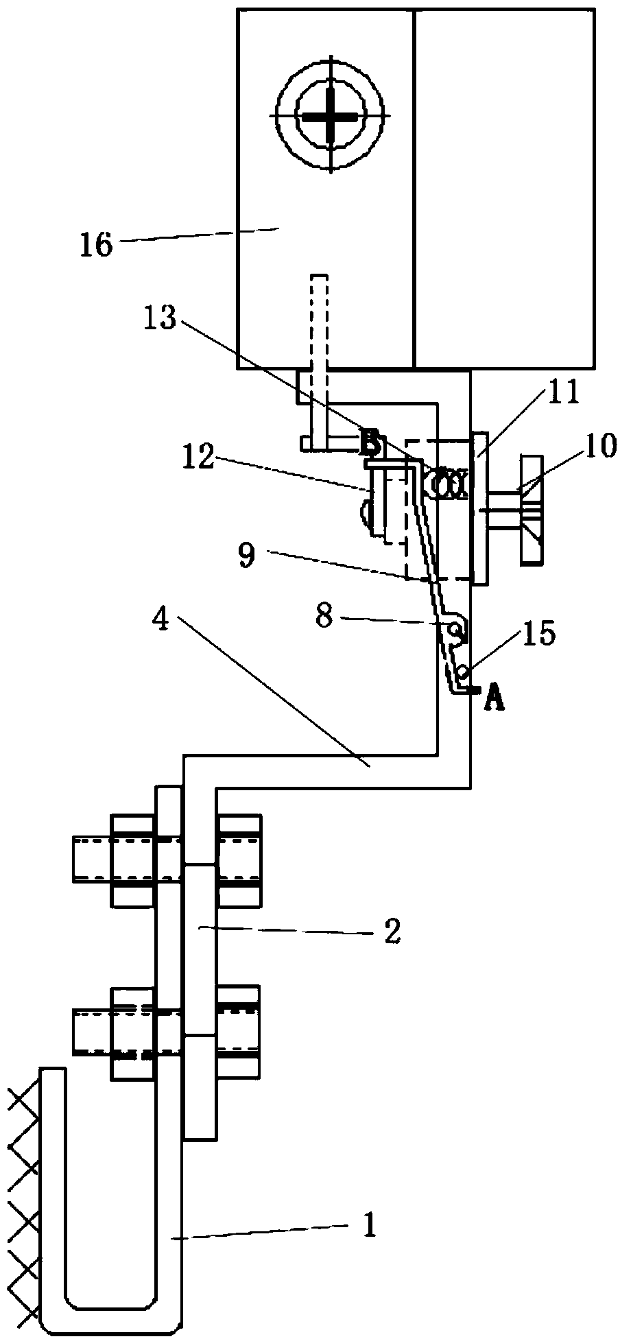
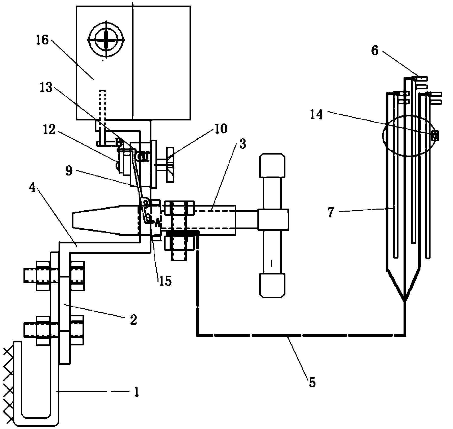
[0022] The grounding sequence lock of the present invention will be described in further detail below in conjunction with the accompanying drawings and specific embodiments.

[0023] As shown in the figure, the present invention is a grounding sequence lock for temporary safety grounding of wires, busbars, and electrical equipment controlled by high-voltage switches or isolating switches in power plants, substations, and power distribution fields. It is a safety control device for temporary grounding. It includes a grounding connector 2 connected to the grounding grid. The grounding grid can be connected to the grounding connector 2 through the grounding grid connector 1. The grounding grid connector 1 is generally welded on the main grounding grid. It can be connected to the main grounding grid with bolts; the grounding connector 2 is provided with a connecting section 4 that can be connected to the grounding clip 3, and the grounding clip 3 is connected to the grounding rod 7...


PUM


Abstract

The invention discloses a grounding sequence lock. The grounding sequence lock comprises a grounding connecting piece used for being connected with a grounding grid, wherein the grounding connecting piece is provided with a connecting piece, a grounding clamp is connected with a grounding rod through a grounding wire, the grounding rod is provided with a grounding hook, a hinge shaft is arranged on the side face of the connecting section, and a pressure control rod is hinged to the hinge shaft. A grounding control lock is arranged on the grounding connecting piece, a rotating shaft of the grounding control lock can rotated to be switched between an unlocking position and a locking position, an unlocking key can be pulled out only in the unlocking position, and the rotating shaft of the grounding control lock is connected with a grounding control hook. A spring is arranged between the pressure control rod and the grounding connecting piece, a three-phase-interlocking locking device is arranged on the grounding rod, and the interlocking key further can open or lock the three-phase-interlocking locking device. The grounding sequence lock has the advantages of being convenient to install, flexible in use and capable of controlling and guiding a grounding operator to accurately perform grounding operation, eliminates potential safety hazards, meets sequence requirements for assembling and disassembling the grounding wire through safe technical measures and meets needs for site operation.

Description

[0001] technical field [0002] The invention relates to a device for temporary safety grounding in power distribution systems such as power plants and substations, in particular to a grounding sequence lock. Background technique [0003] At present, the temporary grounding electromagnetic locks and other temporary grounding locks used in power generation, supply and distribution systems have the following common problems: [0004] 1. Hanging the grounding wire is a safety precaution adopted after a power failure. If the grounding wire is not used or used incorrectly, and the wrong grounding method cannot be restricted by the operator (incorrect use of the grounding operation sequence), accidents will often increase. chance of [0005] 2. It is difficult to operate to connect the ground grid through a special grounding pin, and the locking pressure of the grounding pin is artificially affected, which may cause the contact area to fail to meet the use requirements; [0...

Claims


Application Information

Patent Timeline
Patent Type & Authority Applications(China)
IPC IPC(8): H02B3/00
Inventor 戴锋孙文凯华伟杨广才黄涛姬俊鹏周斌全廖英祺李迎涛周鹏陈从武史荛
Owner 溧阳市科燕新技术开发所
Why Eureka
Try Eureka