Dispensing method and device for dispensing

An applicator, liquid technology, applied in the field of devices for performing the method, can solve the problems of large second liquid, consumption, etc., and achieve the effect of easy expansion

Active Publication Date: 2014-01-01
LIQUAVISTA BV
View PDF7 Cites 2 Cited by
  • Summary
  • Abstract
  • Description
  • Claims
  • Application Information

AI Technical Summary

Problems solved by technology

[0003] The disadvantage of this known method is that it consumes a large amount of the second liquid and all the surfaces of the support plate are covered by the second fluid, however, the covering of only one surface is necessary

Method used


Image

  • Dispensing method and device for dispensing
  • Dispensing method and device for dispensing
  • Dispensing method and device for dispensing

Examples


Embodiment Construction

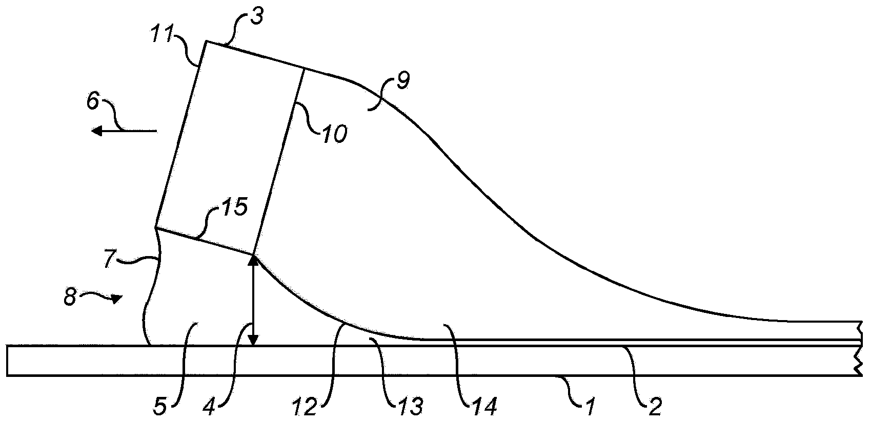
[0033] figure 1 An embodiment of a device for depositing a first liquid layer on a surface using the method according to the invention is shown in cross-section. Plate 1 , also shown in cross-section, has a surface 2 on which a first liquid layer is deposited. An applicator 3 in the form of a rod or slide is suspended above the surface 2 . The applicator and the surface form a gap 4 indicated by an arrow in the figure, which shows the minimum distance between the applicator and the surface. The applicator has a major axis perpendicular to the plane of the figure; the gap is elongated in the direction of the major axis. The gap is filled with elongated beads 5 of the first liquid.

[0034] In operation, slide 3 is moved over surface 2 in direction 6 . The water drop 5 has a front interface 7 with the gas 8 in front of the applicator 3 . Interface 7 extends from surface 2 to applicator 3 . A volume 9 of the second liquid having an elongated shape is only arranged on the tr...


PUM


Abstract

A method provides a layer of a first liquid on a first area of a surface using an elongate applicator, an elongate gap being formed between the applicator and the surface, the gap being filled with an elongate globule of the first liquid, and an amount of a second liquid being arranged in contact with the applicator and with the globule, the first liquid and the second liquid being immiscible and the first area having a higher wettability for the first liquid than for the second liquid. The method includes applying a relative motion between the applicator and the surface, wherein the amount of second liquid being arranged only on a trailing side of the applicator.

Description

technical field [0001] The invention relates to a method for providing a layer of a first liquid on a first area of ​​a surface by means of a dispenser. The invention also relates to a device for carrying out the method. Background technique [0002] A method of providing a first fluid layer on a surface area of ​​a support plate for electrowetting displays is known from the international application WO 2010 / 133690. In this method, the diagonal support plate is soaked in a second fluid that is immiscible with the first fluid. The second fluid forms grooves near the surface of the support plate, filling the grooves with the first fluid. By increasing the height of the second fluid relative to the surface, the groove is moved along the surface. The surface is initially covered with air, then covered with the first fluid, and finally submerged in the second fluid. When the second fluid covers the entire support plate, the first fluid forms a thin layer on the surface area b...

Claims


Application Information

Patent Timeline
Patent Type & Authority Applications(China)
IPC IPC(8): G02B26/02B05C11/02B05D1/00G03F7/16
CPCB05D1/007B05C5/0212B05B1/14G03F7/0037B05C5/0254G02B26/004B05C9/06G02B26/00G02B26/02G02B25/004
Inventor 约翰·格雷戈里詹森·哈尔克伊瓦·施拉姆
Owner LIQUAVISTA BV
Why Eureka
Try Eureka