Electromechanical switching device

A switchgear and electromechanical technology, applied in the field of arc extinguishing devices, can solve the problems of small electromagnetic force and small electromagnetic field, and achieve the effects of reducing logistics costs, fast extinguishing, and high variability

Active Publication Date: 2014-03-26
SIEMENS AG
View PDF10 Cites 2 Cited by
  • Summary
  • Abstract
  • Description
  • Claims
  • Application Information

AI Technical Summary

Problems solved by technology

However, the disadvantage of the arc blowing circuit is that only a small electromagnetic field is generated in

Method used


Image

  • Electromechanical switching device
  • Electromechanical switching device
  • Electromechanical switching device

Examples


Embodiment Construction

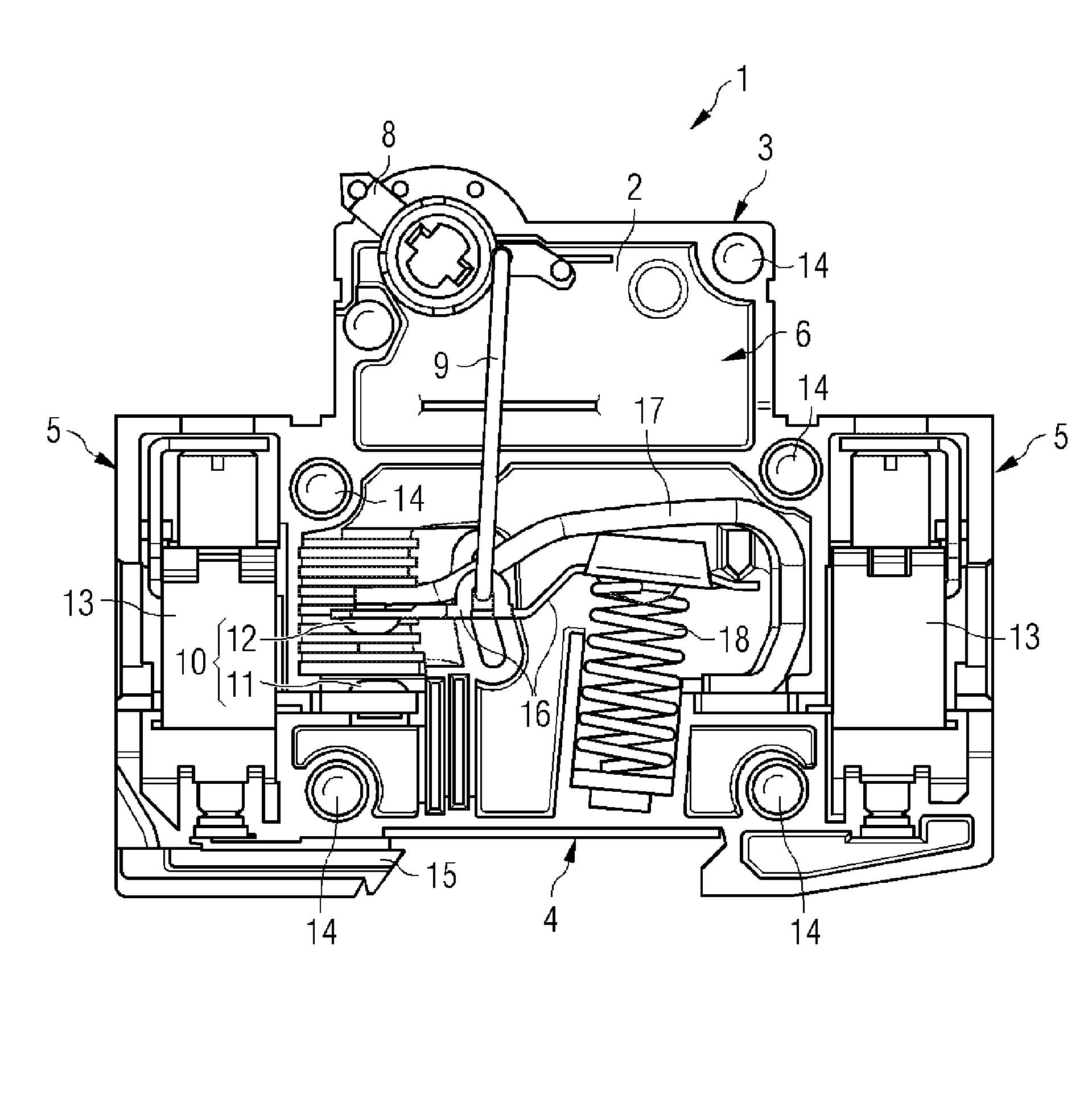
[0027] figure 1 A schematic illustration of the switching device 1 is shown in a side view. The switching device 1 has a housing 2 which is essentially formed from two housing half-shells which are connected to form the housing 2 by means of a plurality of riveted connections 14 . In this case, in figure 1 The open switching device 1 is shown in , that is to say the front housing half shell of the housing 2 has been removed in this illustration. The housing 2 has a front side 3 on which an operating element 8 is arranged for manually operating the switching device 1 . A fastening side 4 of the housing 2 is formed opposite the front side 3 and serves to fasten the switching device on a carrier rail (not shown), for example a top rail. For this purpose, a manually actuatable slide 15 is arranged on the housing 2 for engaging behind the carrier rail. In this way, the switchgear 1 can be quickly and easily fastened to the carrier rail or released again from the carrier rail. ...


PUM


Abstract

An electromechanical switching device according to the present invention has a switch contact used for interrupting an electrical line, and an arc extinguishing device for extinguishing an arc generated during opening of an energized switch contact. The arc extinguishing device has a first permanent magnet and a second permanent magnet which are arranged opposite to each other at two sides of the switch contact and are magnetized in opposite directions in the way of repelling each other. A magnetic field which is superimposed with the arc generated during opening of the energized switch contact is generated through the first permanent magnet and the second permanent magnet. The resulting magnetic field exerts an electromagnetic force on the arc, while the force vector of the electromagnetic force is depended on the polarity of a current. The force vector always has a directional component regardless of the polarity of the arc, the directional component pushes the arc away from the switch contact. The arc extinguishing device and the switching device with the arc extinguishing device can be used for both DC and AC.

Description

technical field [0001] The invention relates to an electromechanical switching device having a switching contact for interrupting an electrical line and an arc extinguishing device for extinguishing an arc which occurs when the energized switching contact opens. The term switching device is to be understood here not only as a protective switching device, such as a power switch, a circuit breaker or a fault current switch, but also as a switching device without its own protective function, such as a load switch, disconnector or load disconnector. Background technique [0002] Different types of protective switching devices are known from the prior art: Power switches are specially designed for high currents. A line breaker (so-called LS switch) is an overcurrent protection device used in electrical installations and in particular in the field of low-voltage networks. The power switch and the line protection switch ensure reliable disconnection in the event of a short circuit...

Claims


Application Information

Patent Timeline
IPC IPC(8): H01H9/44
CPCH01H9/36H01H9/443
Inventor T.霍赫姆特R.许廷格
Owner SIEMENS AG
Why Eureka
Try Eureka