Impression cylinder and imprinting system having such an impression cylinder

A technology of embossing cylinders and cylinders, applied in printing, printing machines, rotary printing machines, etc., can solve the problems of impossible clamping force adjustment, time-consuming, clamping system clearance, etc., and achieve the effect of ensuring length compensation

Active Publication Date: 2017-03-22
GALLUS FERD RUESCH
View PDF6 Cites 0 Cited by
  • Summary
  • Abstract
  • Description
  • Claims
  • Application Information

AI Technical Summary

Problems solved by technology

[0005] The systems known from the prior art for clamping embossing molds or embossing sleeves have the disadvantage that either no adjustment of the clamping force is possible or that these clamping systems have the possibility of gap shown
Said clamping is also generally time-consuming, especially when a large number of mechanical parts have to be manipulated

Method used


Image

  • Impression cylinder and imprinting system having such an impression cylinder
  • Impression cylinder and imprinting system having such an impression cylinder
  • Impression cylinder and imprinting system having such an impression cylinder

Examples


Embodiment Construction

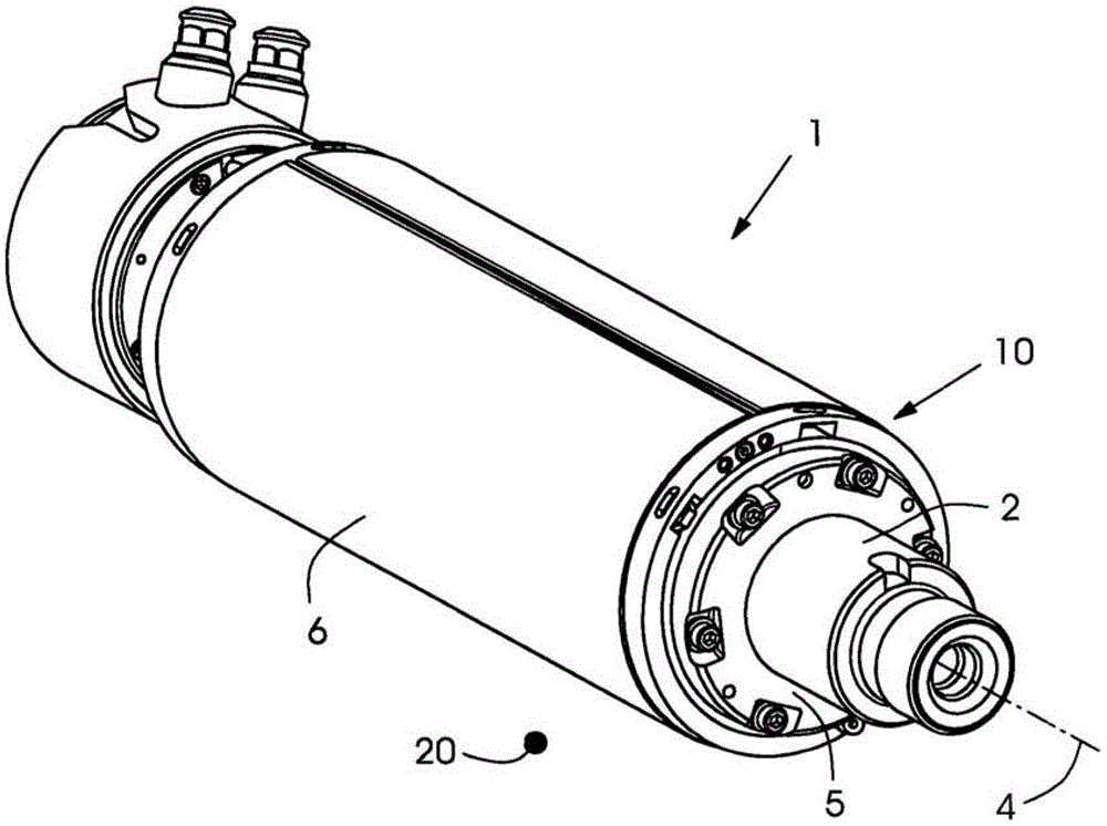
[0022] figure 1 Shown is a hot-foil embossing cylinder 1 which forms an embossing system with a counter-foil embossing cylinder 20 arranged opposite a printing material web, not shown. The printing material web runs between the two cylinders 1 , 20 and is embossed there by means of the embossing die 6 . The hot foil embossing cylinder 1 has an embossing cylinder 5 with an embossing mold 6 and clamped on a clamping shaft 2 with an axis of rotation 4 . In order to clamp the embossing mold 6 on the embossing cylinder 5 , a clamping system 10 is provided here, which will be described in more detail with reference to the following figures.

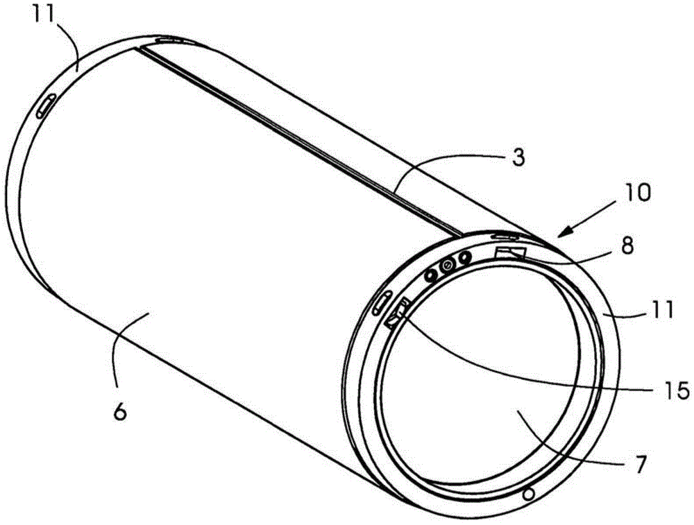
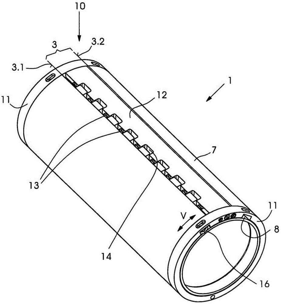
[0023] From figure 2 It can be seen that the embossing mold 6 is clamped on the hollow cylinder 7 by means of the clamping system 10 . For this purpose, the hollow cylinder 7 has at its two ends each a projection 8 on which a bearing ring 11 is supported. The two bearing rings 11 are connected to one another via a carrier part 12 which is ...


PUM


Abstract

The forming cylinder has a hollow cylindrical body having two separating edges oriented in longitudinal direction of the body, such that a lateral surface broken by a gap is formed. A clamping system (10) is provided for expanding the hollow cylindrical body. The clamping system has two rotatable rings mounted on the hollow cylindrical body. The rings are connected by a carrier present in the gap. The spring elements are employed at the carrier and at the former separating edge. The spring force of the spring elements act in circumferential direction of the hollow cylindrical body.

Description

technical field [0001] The invention relates to an embossing cylinder for receiving a sleeve-shaped embossing mold, wherein the embossing cylinder has a hollow cylinder-shaped body. The invention also relates to an embossing system for processing strip-shaped or sheet-shaped elements, which embossing system comprises an embossing cylinder, a clamping shaft, a sleeve-shaped embossing tool and a counter-embossing cylinder. Background technique [0002] In order to produce high-quality folding boxes and labels, it is known to further process the product after printing in a hot foil embossing device and to provide an embossing contour. Here, in order to produce a high-quality appearance of the product, silver or gold foils are often used. [0003] Such a hot foil embossing device is known, for example, from EP 0 982 127 A1, which has a cylinder and a counter cylinder, between which an embossing gap is formed. The material web to be printed and the embossing foil web are moved ...

Claims


Application Information

Patent Timeline
Patent Type & Authority Patents(China)
IPC IPC(8): B41F13/18B41F13/20
CPCB41F19/062B41P2219/33B44B5/0009B44B5/026B44B5/028
Inventor A·延克M·奥尔蒂兹S·哈德格
Owner GALLUS FERD RUESCH
Why Eureka
Try Eureka