Method and control circuit for controlling brushless motor

A technology of control circuit and intermediate circuit, applied in control system, current controller, motor control and other directions, can solve problems such as increasing cost, and achieve the effect of reducing power consumption, easy implementation, and reducing standby operation.

Active Publication Date: 2019-08-09
穆尔芬根依必派特股份有限公司
View PDF2 Cites 0 Cited by
  • Summary
  • Abstract
  • Description
  • Claims
  • Application Information

AI Technical Summary

Problems solved by technology

[0004] In practical use of this type of EC motor, problems can arise if not all components are configured for particularly high voltages and currents, especially due to overvoltages and overcurrents on the mains side; however, the All components configured for extremely high voltages and currents add cost

Method used


Image

  • Method and control circuit for controlling brushless motor
  • Method and control circuit for controlling brushless motor
  • Method and control circuit for controlling brushless motor

Examples


Embodiment Construction

[0014] For the following description it is expressly emphasized that the invention is not limited to the embodiments and not to all or a plurality of features of the described feature combinations. In fact, each individual partial feature of an embodiment can be inventive in itself and also in combination with any other feature, even when separated from all other partial features described in relation.

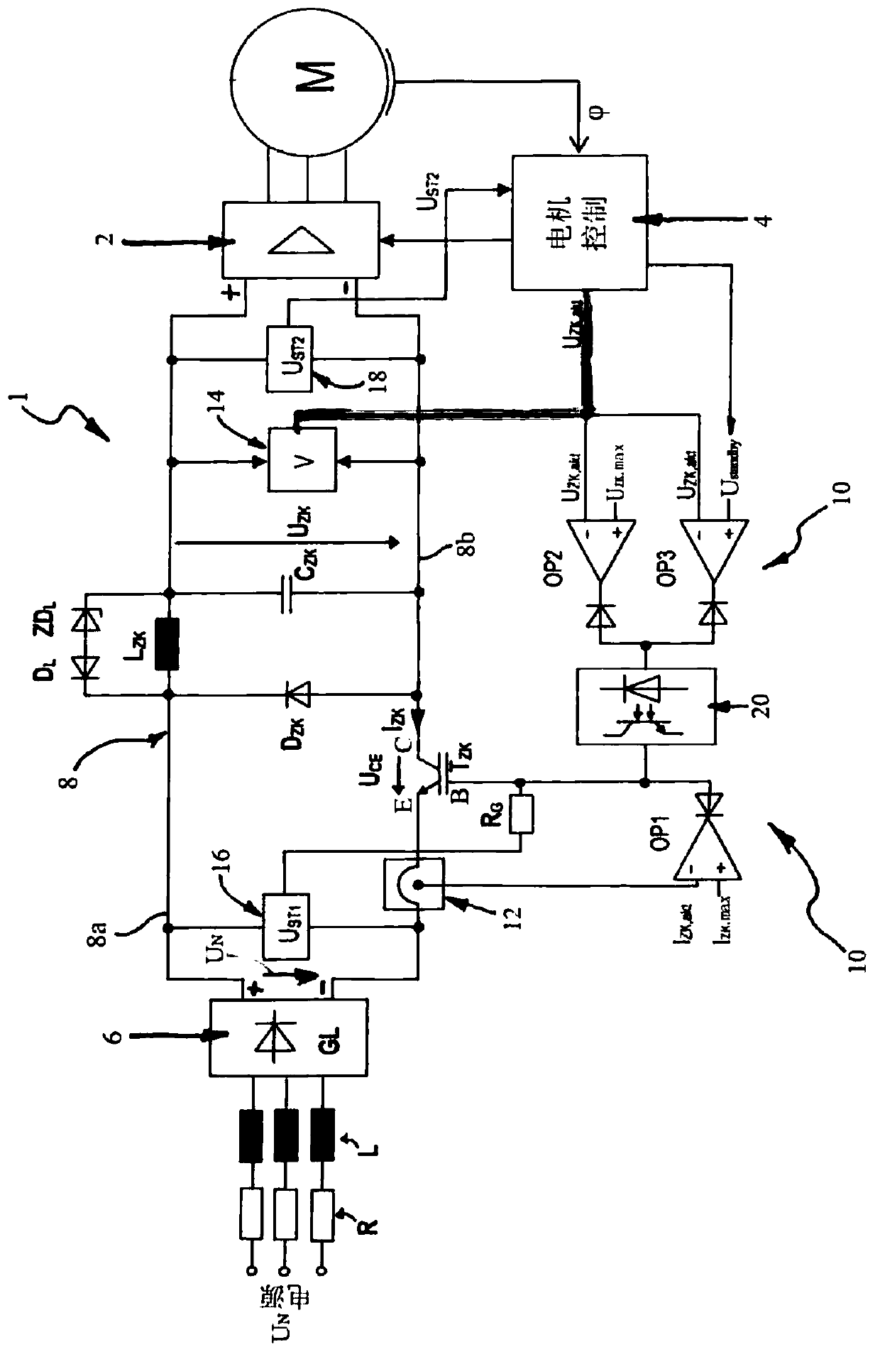
[0015] according to figure 1 , the control circuit 1 according to the present invention is used to control the motor M, which is schematically drawn in a very simplified form, and is preferably a three-strand permanent magnet excitation synchronous motor, abbreviated as "PMSM", that is, in fact is a three-phase motor, however, the three-phase motor is operated with DC voltage via a controlled inverter 2 . Motors of this type M are therefore often also referred to as brushless electronically commutated DC motors or EC motors for short.

[0016] The inverter 2 is constructed a...


PUM


Abstract

The invention discloses a method for controlling a brushless electronically commutated motor, the mains AC voltage (U N ) is rectified into an intermediate circuit DC voltage (U ZK ), the DC voltage (U ZK ) consists of an intermediate circuit capacitor (C ZK ) is fed to an inverter controlled by a motor control device for feeding and commutating the motor, the DC intermediate circuit voltage (U ZK ) voltage level is monitored and compared to a predetermined limit (U ZK,max / U Standby ) for comparison, once the limit is reached or exceeded (U ZK,max / U Standby ), the intermediate circuit DC voltage (U ZK ) is limited to said predetermined limit by timing disconnection and reconnection. The method and control circuit of the present invention have high functional reliability and can operate economically.

Description

technical field [0001] According to the preamble of independent claim 1, the invention relates firstly to a method for controlling a brushless electronically commutated motor, in which the mains AC voltage is rectified into an intermediate circuit DC voltage which is supplied by a circuit comprising an intermediate circuit capacitor The intermediate circuit of the motor is fed to an inverter, and the inverter is controlled by the motor control device to feed and commutate the motor. [0002] According to the preamble of claim 5, the invention also relates to a corresponding control circuit comprising a mains rectifier, an intermediate circuit connected downstream to a positive line and a negative line, and an inverter, the inverter The converter is fed with an intermediate circuit DC voltage from the intermediate circuit and can be controlled by the electronic motor control to commutate the motor; an intermediate circuit capacitor is arranged in the intermediate circuit. Bac...

Claims


Application Information

Patent Timeline
Patent Type & Authority Patents(China)
IPC IPC(8): H02P29/02
CPCH02P29/027H02P2201/11H02P29/0241H02P6/28
Inventor 丹尼尔·康尼格托马斯·布朗
Owner 穆尔芬根依必派特股份有限公司
Why Eureka
Try Eureka