

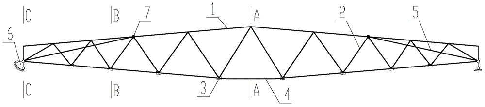
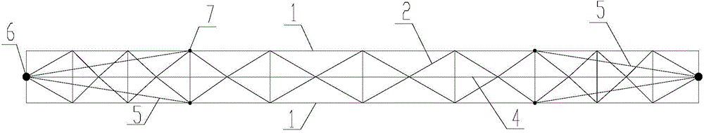
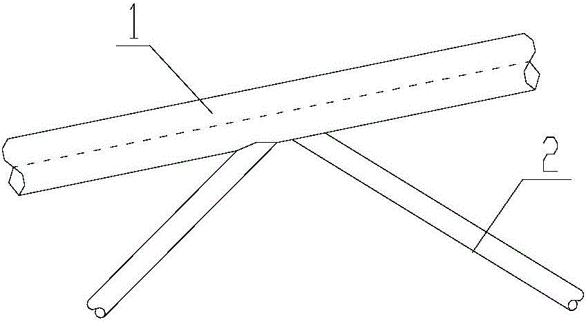
Truss string structure internally provided with inclined guy ropes
A string truss and stay cable technology is applied in the field of large-span stringed roof structures, which can solve the problems of increased construction auxiliary equipment, no self-balancing system, and inability to adapt to wind suction, etc., and achieves low steel consumption and structural stability. Good, low-cost effect
- Summary
- Abstract
- Description
- Claims
- Application Information
AI Technical Summary
Problems solved by technology
Method used
Image

Examples
Embodiment Construction
[0030] In order to make the purpose and technical solutions of the embodiments of the present invention more clear, the technical solutions of the embodiments of the present invention will be clearly and completely described below in conjunction with the drawings of the embodiments of the present invention. Apparently, the described embodiments are some, not all, embodiments of the present invention. Based on the described embodiments of the present invention, all other embodiments obtained by persons of ordinary skill in the art without creative efforts shall fall within the protection scope of the present invention.
[0031] Those skilled in the art can understand that, unless otherwise defined, all terms (including technical and scientific terms) used herein have the same meaning as commonly understood by one of ordinary skill in the art to which this invention belongs. It should also be understood that terms such as those defined in commonly used dictionaries should be und...
PUM
 Abstract
Description
Claims
Application Information