Ice machine with snakelike refrigerating coil system

A serpentine coil, ice machine technology, applied in ice making, ice making, lighting and heating equipment and other directions, can solve problems such as damage, affecting the quality of ice making, accidental knocking of door openings, etc., to maintain ventilation, Enhance the efficiency of ice making and increase the effect of ice making

Active Publication Date: 2014-10-15
青岛澳润商用设备有限公司
View PDF6 Cites 4 Cited by
  • Summary
  • Abstract
  • Description
  • Claims
  • Application Information

AI Technical Summary

Problems solved by technology

However, the ice machine used for ships is generally small in size, and the temperature and humidity in the cabin are high. In addition, the ice machine itself is small in size, and the heat conduction efficiency of air is low, so that the heat generated by the ice machine in the ice process is poor. It cannot be dissipated as soon as possible, resulting in the timely increase of the refrigeration system, and the temperature inside the ice maker cannot be reduced rapidly, and the ice production capacity of the small ice maker cannot be increased.
[0003] In addition, due to the bumpy transportation environment of the traditional marine ice machine, accidental bumps and damages often occur when the door is opened.
Moreover, when the product is not in use for a long time, the closed door is likely to cause bacteria to grow on the ice maker and the door seal due to the special humid and airtight environment, which will affect the quality of ice making and make the produced ice cubes unsanitary. Assure
And the door lock in the prior art also does not have the function of adjusting the distance between the door body and the cabinet body, which brings a lot of inconvenience to the user

Method used


Image

  • Ice machine with snakelike refrigerating coil system
  • Ice machine with snakelike refrigerating coil system
  • Ice machine with snakelike refrigerating coil system

Examples


Embodiment Construction

[0028] The present invention provides an ice maker with a serpentine refrigeration coil system. In order to make the purpose, technical solution and effect of the present invention clearer and clearer, the present invention will be further described in detail below. It should be understood that the specific embodiments described here are only used to explain the present invention, not to limit the present invention.

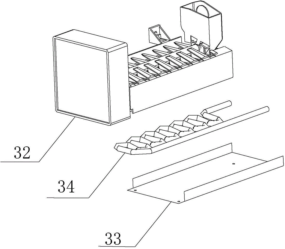
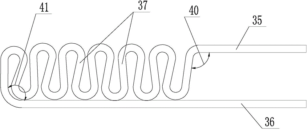
[0029] The present invention provides an ice maker with a serpentine refrigeration coil system such as figure 1 , figure 2 As shown, it includes an ice maker 32, an evaporator plate 33 is arranged under the ice maker 32, an installation space is formed between the evaporator press plate 33 and a side wall of the ice maker 32, and a serpentine shape is arranged in the installation space. The coiled pipe 34, the serpentine coiled pipe 34 includes a first straight pipe 35 and a second straight pipe 36, the first straight pipe 35 and the second straight pipe 36 are...


PUM


Abstract

The invention discloses an ice machine with a snakelike refrigerating coil system. The ice machine comprises an ice maker. An evaporator pressure plate is arranged below the ice maker. A mounting space is formed by the evaporator pressure plate and one side wall of the ice maker. A snakelike coil is arranged in the mounting space, and consists of a first straight pipe and a second straight pipe, wherein the first straight pipe and the second straight pipe are communicated through a bent pipe; the joint of the first straight pipe and the bent pipe is in an arc shape having a central angle being 90 to 100 degrees; and the joint of the second straight pipe and the bent pipe is in an arc shape having a central angle being 40 to 60 degrees. The first straight pipe, the bent pipe and the second straight pipe are positioned on one plane to form a reclining surface which is tightly reclined on the corresponding side wall through heat-conducting silica gel. The snakelike coil is pressed against on the back surface of the ice maker, and the ice maker and the snakelike coil are fixed to an integrated structure by using the heat-conducting silica gel, so that the transfer of cold needed by the ice maker is increased, and the ice making capacity can be increased by 20% with the refrigeration system of the ice machine remaining unchanged.

Description

technical field [0001] The present invention relates to an ice maker with a serpentine refrigeration coil system. Background technique [0002] The ice machine is a device that uses water as a carrier to produce ice after passing through a certain device in the electrified state. According to the principle of the evaporator and the different production methods, the shape of the ice cubes generated is also different. Generally, according to the shape of the ice, ice machines are divided into granular ice machines, flake ice machines, plate ice machines, tube ice machines, shell ice machines, etc. . However, the ice machine used for ships is generally small in size, and the temperature and humidity in the cabin are high. In addition, the ice machine itself is small in size, and the heat conduction efficiency of air is low, so that the heat generated by the ice machine in the ice process is poor. It cannot be dissipated as soon as possible, resulting in the timely increase of...

Claims


Application Information

Patent Timeline
Patent Type & Authority Applications(China)
IPC IPC(8): F25C1/00
CPCY02P60/85
Inventor 张进富彭丙艳徐涛刘丙伟
Owner 青岛澳润商用设备有限公司
Why Eureka
Try Eureka