Voltage balancing detection apparatus for electric locomotive rectifier cabinet

A technology for detection devices and electric locomotives, applied to measuring devices, measuring current/voltage, measuring electrical variables, etc., can solve problems such as low efficiency, danger, electric shock, etc., to avoid electric shock, improve work efficiency, and record data conveniently Effect

Inactive Publication Date: 2014-12-24
CRRC LUOYANG CO LTD
View PDF0 Cites 0 Cited by
  • Summary
  • Abstract
  • Description
  • Claims
  • Application Information

AI Technical Summary

Problems solved by technology

The current measurement method has many shortcomings: 1. During the test, the rectifier cabinet must be connected to high voltage first, and then the operator must approach the rectifier cabinet to measure the voltage of each component on the rectifier cabinet, and the operator is required to wear rubber gloves and insulated shoes.
Obviously this operation is very dangerous, there is a possibility of electric shock
2. Generally, a voltmeter or a multimeter is used for measurement, and the operator needs to hold a test lead in both hands, so a second person is required to hold the test lead beside him.
3. When measuring, it is necessary to measure one component by one component, and record every time a component is measured, which is inefficient
4. During the measurement, due to the different pressure of the contact element of the test pen, etc., the measured data has a large error

Method used


Image

  • Voltage balancing detection apparatus for electric locomotive rectifier cabinet
  • Voltage balancing detection apparatus for electric locomotive rectifier cabinet

Examples


Embodiment Construction

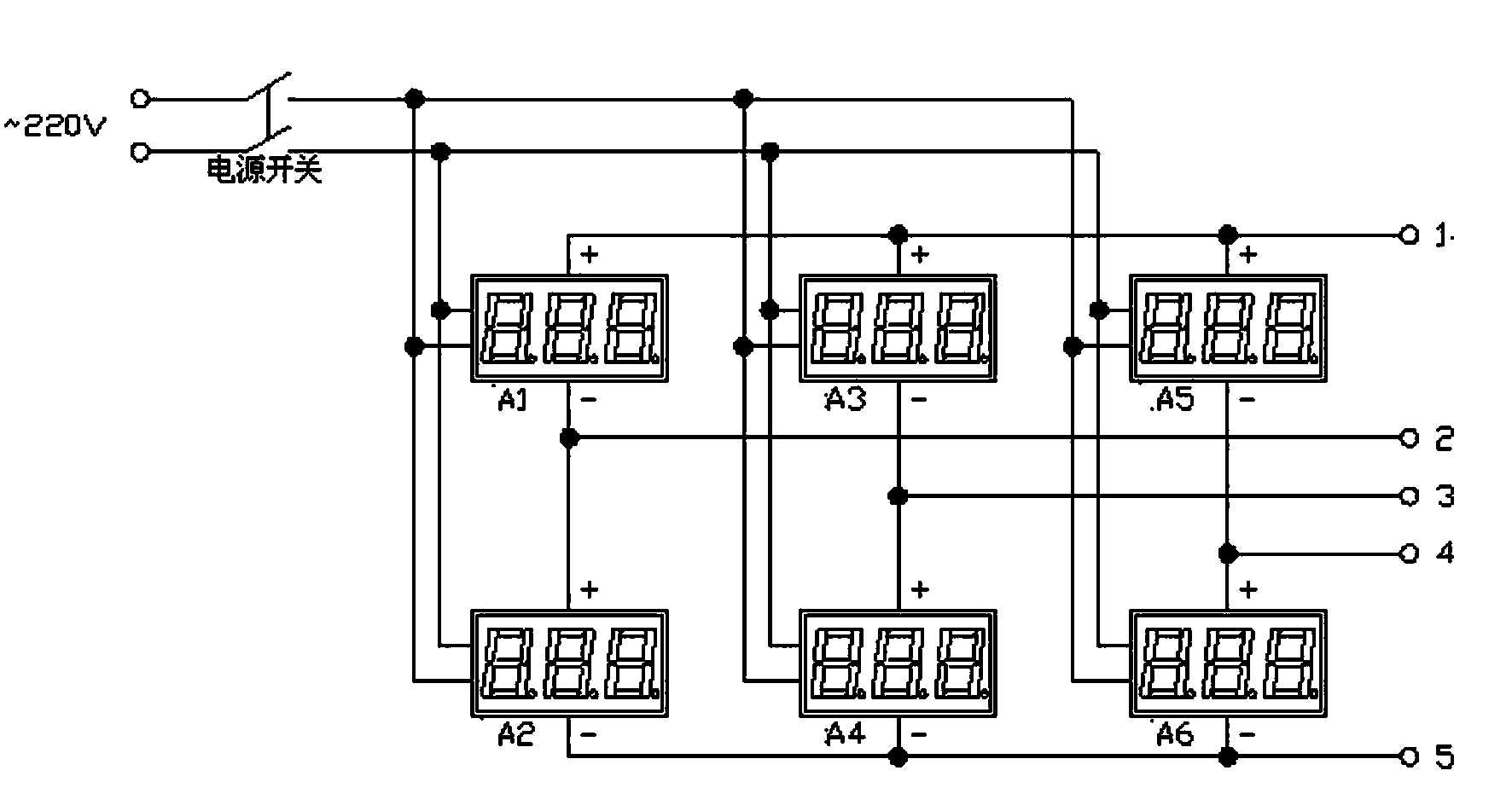
[0010] Such as figure 1 As shown, the present invention adopts every two voltmeters in series to form at least three groups, a total of 6 voltmeters A 1 ~A 6 , the voltmeters are all digital display DC voltmeters, the series contacts of each two voltmeters respectively lead to an external measurement terminal 2, 3, 4, and the positive connection contacts of the voltmeters in series lead to an external measurement terminal 1, and the negative connection The contact leads to an external measuring terminal 5, which is the first group of voltmeters A 1 The negative terminal of the voltage input and the voltmeter A 2 The positive end of the voltage input is connected to the contact and leads to an external measuring end 2. The second group of voltmeters A 3 The voltage input negative terminal of the voltmeter A4 is connected with the voltage input positive terminal of the voltmeter A4 to draw an external measuring terminal 3 . The third group of voltmeter A 5 The voltage inpu...


PUM


Abstract

The invention titled as "voltage balancing detection apparatus for an electric locomotive rectifier cabinet" relates to a detection apparatus for detecting element voltage balancing situations of all branch circuits of all bridge arms of the electric locomotive rectifier cabinet. In the prior art, when electric locomotive rectifier cabinets are repaired, the rectifier cabinets are connected in series and are electrified with the 5200-volt high-voltage alternating current, a voltmeter is used for measuring voltages of all elements respectively, and an operator holds the meter pen to measure the elements one by one, so that problems of dangerous operation, low efficiency and large error occur. However, with the provided voltage balancing detection apparatus, the problems can be solved. According to the invention, each two voltmeters are connected in series to form at least three groups; external measuring terminals are respectively led out from the anode connecting contact points and cathode connecting contact points of the three groups of series voltmeters; and one external measuring terminal is respectively led out from the series connection contact points of each two voltmeters. Therefore, the operator only needs to observe the display values of the detection apparatus without the need to approach the electrified rectifier cabinets, so that the operator electric shock possibility can be eliminated and the efficiency is high.

Description

technical field [0001] The invention belongs to a voltage equalization detection device for a railway locomotive rectifier cabinet, in particular to a detection device for detecting whether the voltages of components on each branch of each bridge arm of an electric locomotive rectifier cabinet are consistent. Background technique [0002] During the repair process of rectifier cabinets of electric locomotives, it is necessary to conduct a voltage equalization test on the repaired rectifier cabinets. The purpose of the test is to detect whether the voltages of the series components on each branch of each bridge arm of the rectifier cabinet are consistent. During the test, two rectifier cabinets are connected in series (Shaoshan 3B locomotive has two rectifier cabinets), and 5200V high-voltage alternating current is passed through, and then the voltage on each component is measured with a voltmeter. The current measurement method has many disadvantages: 1. During the test, the...

Claims


Application Information

Patent Timeline
Patent Type & Authority Applications(China)
IPC IPC(8): G01R19/00
Inventor 刘恒李国宾兰跃国
Owner CRRC LUOYANG CO LTD
Why Eureka
Try Eureka