Novel decorating machine

A printing machine, a new type of technology, applied to printing machines, rotary printing machines, screen printing machines, etc., can solve the problems of affecting the positioning accuracy, breaking the elastic platen, and aggravating the vibration of the elastic platen, so as to avoid the positioning accuracy , prevent dust from entering, and avoid the effect of head-to-head

Active Publication Date: 2015-03-04
SHENZHEN CNTOP DIGITAL EQUIP CO LTD
View PDF7 Cites 28 Cited by
  • Summary
  • Abstract
  • Description
  • Claims
  • Application Information

AI Technical Summary

Problems solved by technology

Generally, the cylinder is used to drive the printing arm up. Due to the rapid movement of the cylinder, the lifting or pressing down of the printing arm will be too fast and vibration will occur, which will cause the relative displacement of the printing arm, the screen frame and the scraper, which will affect the cover. Bit accuracy, which leads to different positions of printed patterns on different fabrics of the same batch
[0003] Moreover, the scraper is also reciprocatingly lifting and pressing down on the printing arm. Combined with the lifting and pressing down of the printing arm, this will cause the screen frame that is not completely stably fixed to jump and affect the printing accuracy. In addition , because the mesh of the screen frame itself cannot be set too small, the pattern printed on the fabric is not delicate enough, and there are pixel particles
[0004] In addition, the above-mentioned scraper, screen frame and other parts used to scrape the cloth are called printing head assembly, and since the elastic platen is supported by the guide rail below it, after the printing head assembly exerts pressure on the elastic platen, it will form The "hard-to-hard" situation will further aggravate the vibration of the elastic platen, and may even cause the elastic platen to break. Moreover, because there is a guide rail under the elastic platen, it cannot be inserted into the finished clothes for printing, which is very inconvenient

Method used


Image

  • Novel decorating machine
  • Novel decorating machine
  • Novel decorating machine

Examples


Embodiment Construction

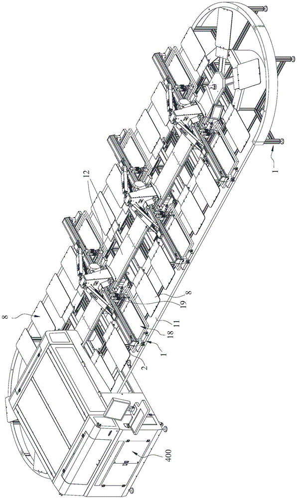
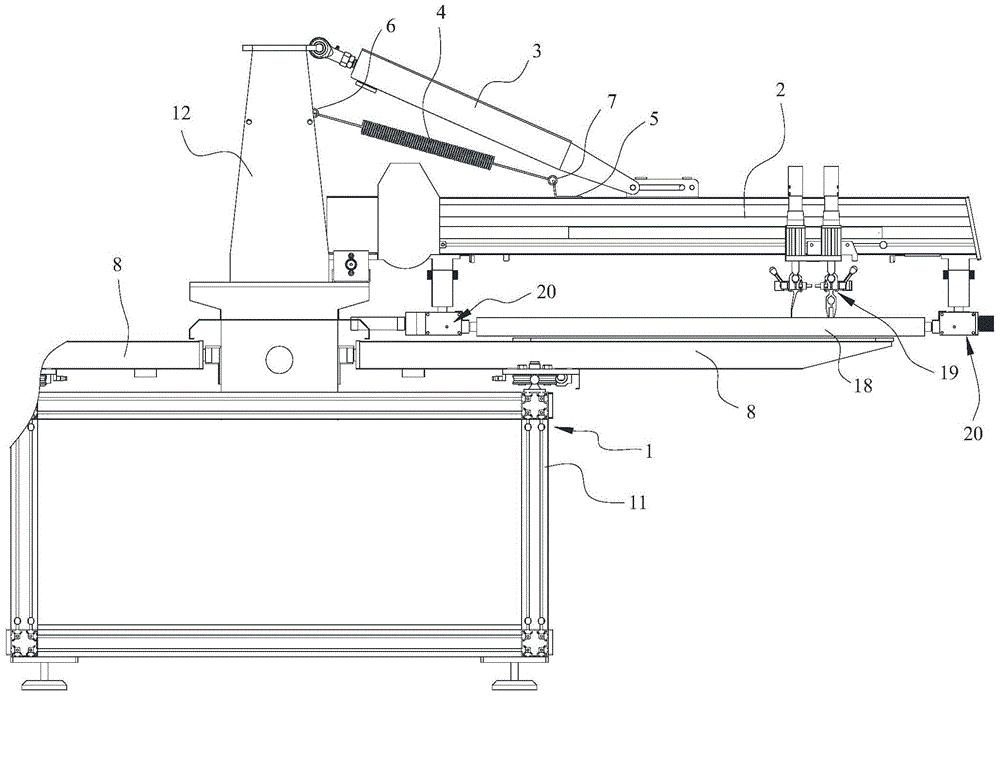
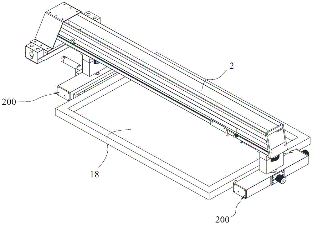
[0034] Such as Figure 1~3A new type of printing machine is shown, including a stand 1, a printing arm 2, a cylinder 3, a tension spring 4, an elastic platen 8, a screen frame 18, a scraper 19 slidingly fitted to the printing arm 2 and a blade fixed to the printing arm 2 The screen frame fixing device 20, the stand 1 includes a frame foot 11 and a fixed arm 12 fixed on the frame foot 11, the fixed arm 12 is linear, and the frame foot 11 is wound around the outer circumference of the fixed arm 12, which can be specifically wound into Oval; one end of the printing arm 2 is hinged to the lower part of the fixed arm 12, the piston rod of the cylinder 3 is stretched out from one end of the cylinder body of the cylinder 3 and is hinged to the upper end of the fixed arm 12, and the other end of the cylinder body of the cylinder 3 is connected to the printing arm 2 The middle part is hinged and slides with the printing arm 2 along the length direction of the printing arm 2; one end of...


PUM


Abstract

The invention discloses a novel decorating machine. The novel decorating machine comprises a table rack, a printing arm, a cylinder, an extension spring, an elastic table plate, a screen frame, a scraper, and a screen frame fixing device, wherein the table rack comprises a rack leg and a fixed arm fixed on the rack leg, the fixed arm is linear, the rack leg wounds the periphery of the fixed arm, one end of the printing arm is hinged to the lower portion of the fixed arm, a piston rod of the cylinder extends out of one end of a cylinder body of the cylinder to be hinged to the upper end of the fixed arm, the other end of the cylinder body of the cylinder is hinged to the middle of the printing arm and is in sliding match with the printing arm in the direction of the length of the printing arm, one end of the extension spring is connected with the middle of the fixed arm, the other end of the extension spring is connected with the printing arm through a sliding plate, the sliding plate is in sliding match with the printing arm, and the bottom of the elastic table plate is in sliding match with the rack leg. The novel decorating machine is capable of buffering the action performed by the cylinder to lift or press the printing arm, greatly reducing vibration by the aid of an elastic force produced by the elastic table plate, and improving register accuracy.

Description

technical field [0001] The invention relates to a printing machine, in particular to a novel printing machine. Background technique [0002] In the field of printing machines, the scraper needs to move back and forth to scrape the screen frame, so that the dye on the screen frame falls into the cloth on the elastic platen. The scraper is generally installed on the printing arm through the guide rail, and the printing arm is hinged with the frame of the printing machine. After the ink is covered and the plate is moved, that is, after the scraper scrapes a screen frame, the next screen frame enters the scraper from the previous station. At this time, the printing arm needs to be lifted up, and then the screen frame and scraper should be lifted. Generally, the cylinder is used to drive the printing arm up. Due to the rapid movement of the cylinder, the lifting or pressing down of the printing arm will be too fast and vibration will occur, which will cause the relative displace...

Claims


Application Information

Patent Timeline
Patent Type & Authority Applications(China)
IPC IPC(8): B41F15/08B41F15/16B41F15/36B41F15/44
CPCB41J3/4078
Inventor 李其相唐桐泽
Owner SHENZHEN CNTOP DIGITAL EQUIP CO LTD
Why Eureka
Try Eureka