
Device for precisely positioning working gear of motor
A precise positioning and working technology, applied in the direction of electromechanical devices, electrical components, electric components, etc., can solve problems such as incorrect working gears of motors, and achieve the effects of low manufacturing cost, power saving, and convenient installation
- Summary
- Abstract
- Description
- Claims
- Application Information
AI Technical Summary
Problems solved by technology
Method used
Image

Examples
Embodiment Construction
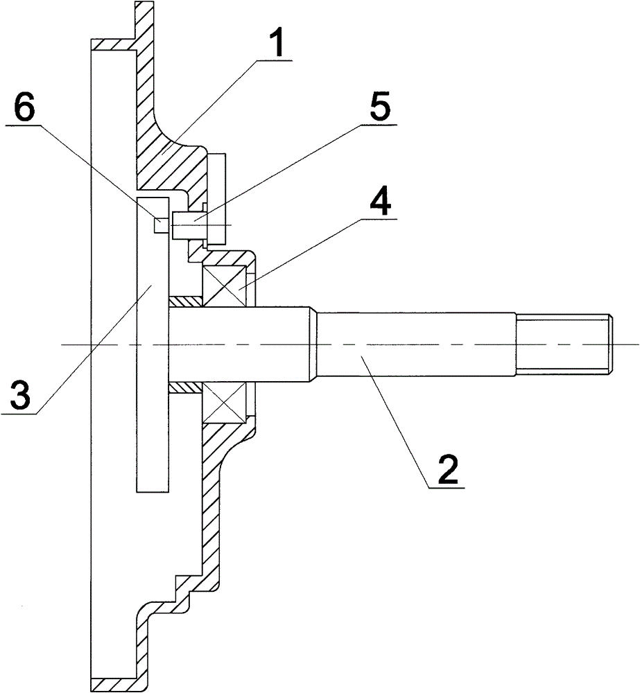
[0009] Such as figure 1 As shown, a device for precisely positioning the working gear of the motor of the present invention includes a gear chamber cover 1, an output shaft 2, and a final gear 3. The final gear 3 is fixedly connected to one end of the output shaft 2, and the other end of the output shaft 2 One end protrudes to the outside of the gear chamber cover 1, the output shaft 2 forms a rotatable fit with the gear chamber cover 1 through the bearing 4, and the speed induction magnet 6 is installed on the side of the end of the final gear 3, which is connected with the speed induction magnet. The inner side of the gear chamber cover 1 corresponding to the position of the steel 6 is fixedly installed with a Hall speed sensor 5 .
[0010] It should be noted that the above descriptions are only preferred embodiments of the present invention, and are not intended to limit this embodiment. Any modifications, equivalent replacements, improvements, etc. made within the spirit a...
PUM
 Abstract
Description
Claims
Application Information