Ball roller bearing

A ball roller and bearing technology, applied in the field of single-row ball roller bearings, can solve the problems of aggravated bearing wear, aggravated swing motion and reciprocating motion, aggravated cage ribs, etc., and achieves the improvement of spring action and lubricant distribution. Effect

Active Publication Date: 2015-05-27
SCHAEFFLER TECH AG & CO KG
View PDF5 Cites 0 Cited by
  • Summary
  • Abstract
  • Description
  • Claims
  • Application Information

AI Technical Summary

Problems solved by technology

In addition, during the operation of the bearing, at the point of contact between the sides of the ball rollers and the ribs of the cage, there is increased wear on the ribs of the cage due to material extrusion and material stripping. Due to this wear, The ball rollers are no longer guided correctly in the axial direction on both sides and thus tend to lead to increased pivoting and to-and-fro movements
This oscillating and to-and-fro movement of the ball rollers then increases the friction and thus the bearing temperature, which is accompanied by increased bearing wear and ultimately leads to failure of the ball roller bearings

Method used


Image

  • Ball roller bearing
  • Ball roller bearing
  • Ball roller bearing

Examples


Embodiment Construction

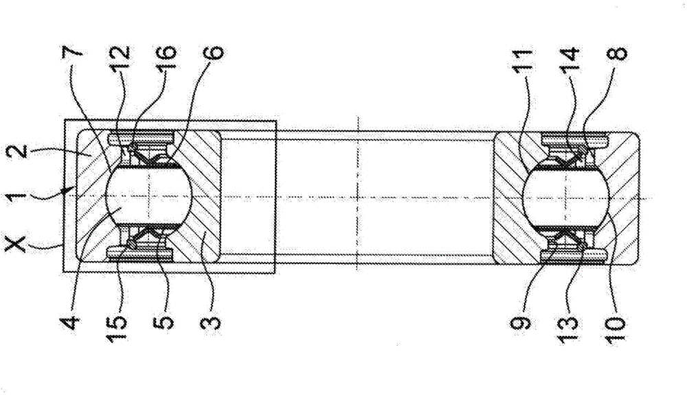
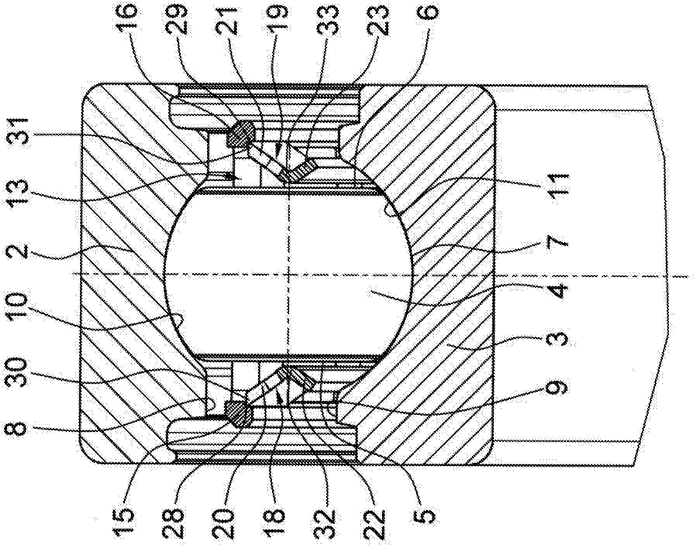
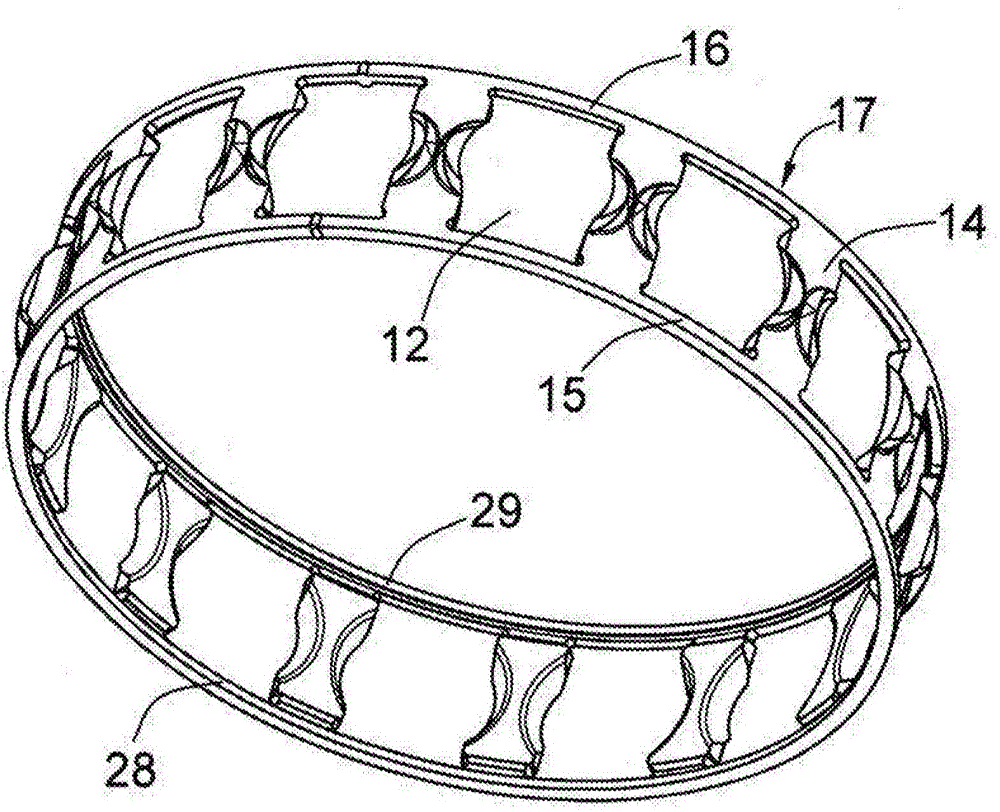
[0020] Depend on figure 1 and 2 A single-row ball roller bearing 1 is clearly shown, which is mainly composed of an outer bearing ring 2 and an inner bearing ring 3 and a plurality of bearing rings 2, 3 arranged between the bearing rings 2, 3 and constructed with two in each case of a spherical base. The ball rollers 4 are formed with flattened, parallel flanks 5 , 6 , which with their running surfaces 7 extending between the flanks 5 , 6 are machined on the inner side 8 of the outer bearing ring 2 and the inner bearing. The groove-shaped raceways 10 , 11 in the outer side 9 of the ring 3 roll and are held in the respective cage pockets 12 of the bearing cage 13 at the same distance from each other in the circumferential direction. The bearing cage 13 here has two side rings 15 , 16 which are connected to one another by a plurality of pocket webs 14 and two cage ribs which are connected to these side rings 15 , 16 and point towards the inner bearing ring 3 . The two cage rib...


PUM


Abstract

The invention relates to a ball roller bearing (1) comprising a plurality of ball rollers (4) arranged between an outer bearing ring (2) and an inner bearing ring (3) and each of which comprises two parallel lateral surfaces (5, 6) and rolls, with their running surfaces (7) extending between said lateral surfaces (5, 6), in two groove-shaped raceways (10, 11) worked into the inner side (8) of the outer bearing ring (2) and the outer side (9) of the inner bearing ring (3), and which are held within individual cage pockets (12) of a bearing cage (13). The bearing cage (13) comprises two interconnected lateral rings (15, 16) and two cage ribs which are connected thereto and in guiding contact with said lateral surfaces (5, 6) for the purpose of axially guiding the ball rollers (4). According to the invention, the bearing cage (13) comprises a cylindrical main part (17) consisting of the lateral rings (15, 16) and pocket webs (14) and made of a cold-formable deep drawn steel, said cage ribs being formed from two separate rib rings (18, 19) which consist of a thermally-treated carbon steel and are force and / or form-fittingly connected to the main part (17).

Description

technical field [0001] The invention relates to a single-row ball roller bearing according to claim 1 forming the features of the preamble, which can be used particularly advantageously, for example, as a stationary bearing for an input shaft or an output shaft of a motor vehicle transmission. Background technique [0002] Ball roller bearings are rolling bearings with special rolling elements designed as ball rollers, which, proceeding from a spherical basic shape, have in each case two side faces that are flattened from this spherical basic shape and are arranged parallel to each other, at which The working surfaces of the ball rollers are respectively arranged between the two side surfaces. Ball roller bearings of this type are generally known in very different embodiments as single-, double-, triple- or quadruple-row radial or angular contact ball roller bearings, and due to the special rolling element shape A special cage embodiment is required in order on the one hand...

Claims


Application Information

Patent Timeline
IPC IPC(8): F16C19/26F16C33/36F16C33/46
CPCF16C19/26F16C33/36F16C33/4611F16C2226/74F16C2204/64F16C33/542F16C33/3868F16C33/44
Inventor 厄恩斯特·盖格尔维尔纳·沃思奥特马尔·韦伯罗伯特·法克尔曼
Owner SCHAEFFLER TECH AG & CO KG
Why Eureka
Try Eureka