Display substrate, manufacturing method therefor, and display device

A technology for displaying substrates and regions, applied in semiconductor/solid-state device manufacturing, organic semiconductor devices, electrical components, etc., can solve problems such as different white light devices, brightness and color shift, and difficulty in simultaneous optimization

Active Publication Date: 2015-09-09
BOE TECH GRP CO LTD
View PDF8 Cites 30 Cited by
  • Summary
  • Abstract
  • Description
  • Claims
  • Application Information

AI Technical Summary

Problems solved by technology

[0004] One is the carrier balance problem of two or more light-emitting units connected in series. The position of the recombination zone will drift with the brightness due to different materials, thus causing brightness and color shift;
[0005] The second is that it is difficult to simultaneously optimize two, three or more light-emitting materials in the same device and the same micro-resonant optical cavity length, especially at large viewing angles, which leads to different angular deviations in white light devices.

Method used


Image

  • Display substrate, manufacturing method therefor, and display device
  • Display substrate, manufacturing method therefor, and display device
  • Display substrate, manufacturing method therefor, and display device

Examples


Embodiment Construction

[0050] In order to understand the above-mentioned purpose, features and advantages of the present invention more clearly, the present invention will be further described in detail below in conjunction with the accompanying drawings and specific embodiments. It should be noted that, in the case of no conflict, the embodiments of the present application and the features in the embodiments can be combined with each other.

[0051] In the following description, many specific details are set forth in order to fully understand the present invention. However, the present invention can also be implemented in other ways different from those described here. Therefore, the protection scope of the present invention is not limited by the specific details disclosed below. EXAMPLE LIMITATIONS.

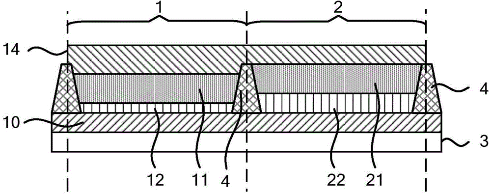
[0052] Such as figure 1 As shown, the display substrate according to one embodiment of the present invention includes:

[0053] A plurality of light-emitting regions (for example, can be arranged o...


PUM


Abstract

The invention discloses a display substrate, a manufacturing method therefor, and a display device. The display substrate comprises a plurality of light-emitting regions, and each light-emitting region comprises a first region and a second region, wherein the first region and the second region are provided with a bottom electrode and a top electrode and share one bottom electrode and one top electrode. The first and second regions of one light-emitting region are respectively provided with light-emitting layers made of the same materials between the bottom electrode and the top electrode of the light-emitting region. Electrical and optical property adjustment layers are respectively disposed between the light-emitting layer and the bottom electrode of each first region and between the light-emitting layer and the bottom electrode of each second region, wherein the electrical and optical property adjustment layers of the first and second regions are different from each other, or the electrical and optical property adjustment layers are respectively disposed between the light-emitting layer and the bottom electrode of each first region and between the light-emitting layer and the bottom electrode of each second region. Through the technical scheme of the invention, the brightness color bias and view angle bias of an organic light-emitting diode can be improved.

Description

technical field [0001] The present invention relates to the field of display technology, in particular, to a display substrate, a method for manufacturing a display substrate, and a display device. Background technique [0002] Tandem white organic light emitting diodes (Tandem White OLED) have high efficiency and do not require high-precision metal mask (fine metal mask, or FMM) or other complicated patterning processes when applied to displays, and are easy to manufacture in large areas and full-color Display and other advantages, has broad application prospects, has been widely concerned by people. [0003] However, tandem white OLEDs lead to several problems because they utilize two, three or more light-emitting materials in the same device: [0004] One is the carrier balance problem of two or more light-emitting units connected in series. The position of the recombination zone will drift with the brightness due to different materials, thus causing brightness and color...

Claims


Application Information

Patent Timeline
Patent Type & Authority Applications(China)
IPC IPC(8): H01L27/32H01L51/52H01L51/56
CPCH10K59/30H10K59/35H10K59/121H10K59/122H10K50/852H10K2102/351H10K59/86H10K59/351H10K50/13H10K50/11H10K50/17H10K50/81H10K59/10H10K71/00H10K50/85H10K59/32
Inventor 许名宏
Owner BOE TECH GRP CO LTD
Why Eureka
Try Eureka