Zoom lens imaging apparatus and method

A zoom lens and imaging method technology, applied in image communication, color TV parts, TV system parts, etc., can solve the problem that the existing performance of the image sensor does not reflect, and does not fundamentally solve the environmental illumination attenuation caused by continuous zoom lenses. problems, etc., to achieve the effect of reducing attenuation and increasing focal length range

Active Publication Date: 2015-10-07
SHENZHEN XINGYUAN TECH CO LTD
View PDF9 Cites 22 Cited by
  • Summary
  • Abstract
  • Description
  • Claims
  • Application Information

AI Technical Summary

Problems solved by technology

[0016] The various compensation methods mentioned above have their own advantages and disadvantages, but they have not fundamentally solved the problem of attenuation of ambient illumination by the continuous zoom lens, and the existing performance of the image sensor has not yet been fully reflected at the long focal point of the lens.

Method used


Image

  • Zoom lens imaging apparatus and method
  • Zoom lens imaging apparatus and method

Examples


Embodiment Construction

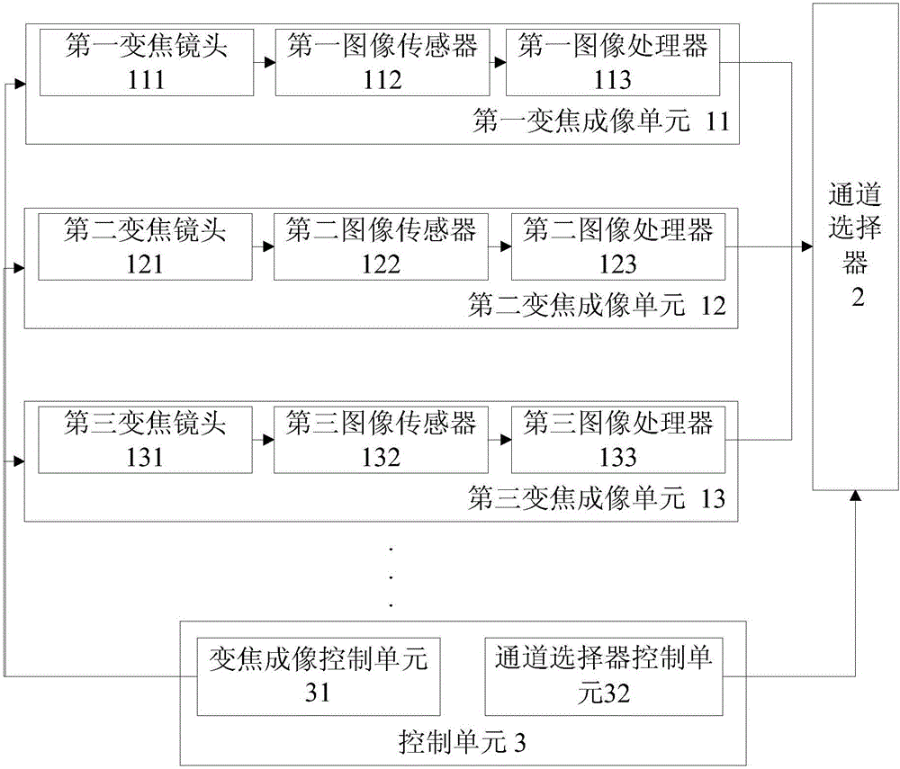
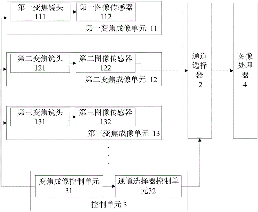
[0048] The zoom lens imaging device of the present invention includes at least two zoom imaging units, a channel selector, and a control unit.

[0049] The focal lengths of each zoom imaging unit increase sequentially, and the focal lengths of two adjacent zoom imaging units partially overlap.

[0050] The channel selector is connected with at least two zoom imaging units, and is used to select the input signal of at least one zoom imaging unit as its output.

[0051] The control unit communicates with the zoom imaging unit and the channel selector respectively. The control unit is used to control the zoom imaging unit for current imaging, the zoom imaging unit for imaging at the next moment, and the pair of zoom imaging units located between the focal lengths of the zoom imaging unit for current imaging and the zoom imaging unit for imaging at the next moment The focal lengths between them overlap sequentially, and the channel selector is also controlled to sequentially swit...


PUM


Abstract

The invention relates to a zoom lens imaging apparatus and method. The apparatus includes at least two zoom imaging units, a channel selector connected with the zoom imaging units; and a control unit connected with the zoom imaging units and the channel selector. Focal lengths of the zoom imaging units increase progressively in sequence, and the focal lengths of two adjacent zoom imaging units partially overlap. The channel selector is used for selecting and taking signals outputted by at least one zoom imaging units as the output. The control unit is used for controlling the focal length between the zoom imaging unit imaging at the moment and the zoom imaging unit imaging at the next moment to sequentially overlap with focal lengths between each two zoom imaging units within the former focal length, and also for controlling the channel selector to switch from taking the zoom imaging unit imaging at the moment as a signal input end sequentially to taking the zoom imaging unit imaging at the next moment as the signal input end. The zoom lens imaging apparatus and method can be used for reducing the attenuation effects of a zoom lens with a wide-range focal length on the environmental illumination.

Description

technical field [0001] The present invention relates to a video imaging device, and more specifically, to a zoom lens imaging device and method. Background technique [0002] Data analysis by the public security department shows that illegal and criminal acts usually occur in areas with low illumination and poor lighting conditions. In terms of crime time, more crimes were committed at night than during the day, accounting for 79.1%. Therefore, after the video image imaging device (hereinafter referred to as the camera) enters the field of public security monitoring, the minimum illumination condition (hereinafter referred to as the low-illuminance performance) of the camera that can meet the basic imaging index has become the goal pursued by users. At the same time, in order to improve the use efficiency of the camera, the maximum range that the camera can see from near to far (hereinafter referred to as coverage) has also become the focus of attention of users. [0003] ...

Claims


Application Information

Patent Timeline
Patent Type & Authority Applications(China)
IPC IPC(8): H04N5/232
CPCH04N23/00H04N23/60
Inventor 伍志坚
Owner SHENZHEN XINGYUAN TECH CO LTD
Why Eureka
Try Eureka