Dehumidifier

A dehumidifier and body technology, applied in the field of dehumidifiers, can solve the problems of knocking down the dehumidifier, heavy weight, high height, etc., and achieve the effects of reduced man-hours, high-end appearance, and reduced manufacturing costs

Active Publication Date: 2015-10-14
LG ELECTRONICS INC
View PDF6 Cites 5 Cited by
  • Summary
  • Abstract
  • Description
  • Claims
  • Application Information

AI Technical Summary

Problems solved by technology

[0007] In this prior art, it is impossible to find a handle or a corresponding structure for the movement of the main body of the dehumidifier itself. In the case of an enlarged dehumidifier, when performing difficult moving operations, its height Higher, which will knock down the dehumidifier, which may threaten the safety of users or damage
[0008] Also, in the case of an enlarged dehumidifier, its weight is heavy, making it difficult to move only by pushing or pulling the main body itself

Method used


Image

  • Dehumidifier
  • Dehumidifier
  • Dehumidifier

Examples


Embodiment Construction

[0053] Hereinafter, specific embodiments of the present invention will be described in detail with reference to the drawings. However, the present invention is not limited to the embodiment that presents the concept of the present invention, and other retrogressive inventions or other embodiments within the scope of the concept of the present invention can be easily proposed by adding, changing, and deleting other structural elements.

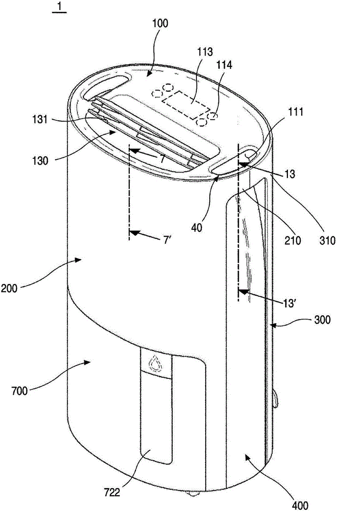
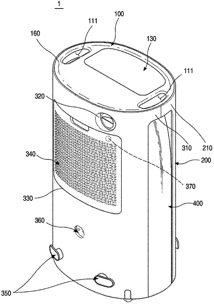
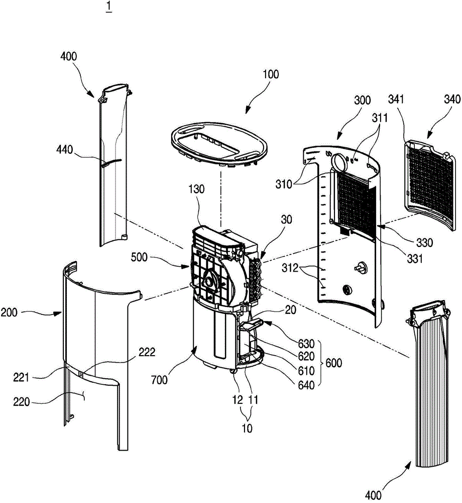
[0054] figure 1 It is the front perspective view of the dehumidifier according to the embodiment of the present invention. and, figure 2 It is the rear perspective view of the above-mentioned dehumidifier. and, image 3 It is an exploded perspective view of the above-mentioned dehumidifier. and, Figure 4 It is a perspective view of the bottom fan assembly in one of the above dehumidifier structures.

[0055] As shown in the figure, the body forming the dehumidifier 1 according to the embodiment of the present invention can have an ellip...


PUM


Abstract

Provided is a dehumidifier in which a handle that is recessed inward from a top surface of a main body to open both side surfaces thereof is disposed to stably move the main body of the dehumidifier without deteriorating an outer appearance of the dehumidifier.

Description

technical field [0001] The present invention relates to dehumidifiers. Background technique [0002] Usually, a dehumidifier is a kind of humid air that sucks the indoor space into the inside of the shell, and makes the above humid air pass through a heat exchanger composed of a condenser and an evaporator flowing with a refrigerant to reduce the humidity, and then re-introduces the humid air to the room. A device that discharges dehumidified air from the space to reduce indoor humidity. [0003] That is, the dehumidifier uses the method of evaporating liquid refrigerant in the evaporator to take heat from the surrounding air. As the refrigerant evaporates, the temperature of the evaporator drops, and the temperature of the air passing through the evaporator also decreases. decline. Therefore, as the temperature around the evaporator drops, the moisture contained in the air is condensed and deposited on the surface of the evaporator in the form of dew, and the dehumidified...

Claims


Application Information

Patent Timeline
Patent Type & Authority Applications(China)
IPC IPC(8): F24F1/02F24F13/20F24F13/00
CPCF24F13/20B65D25/30B65D2525/283F24F1/025F24F3/14F24F3/1405F24F2003/144F24F2003/1446F24F1/02F24F13/00F24F1/022F24F1/04
Inventor 李钟洙李建荣
Owner LG ELECTRONICS INC
Why Eureka
Try Eureka