rice transplanter

A technology of a rice transplanter and a planting arm, which is applied in the fields of transplanting machinery, agriculture, planting methods, etc., can solve the problems of unstable rotation of the drive system, phase deviation of acceleration and deceleration, and poor planting, so as to prevent poor planting and improve Phase deviation, effect of trajectory rationalization

A technology of a rice transplanter and a planting arm, which is applied in the fields of transplanting machinery, agriculture, planting methods, etc., can solve the problems of unstable rotation of the drive system, phase deviation of acceleration and deceleration, and poor planting, so as to prevent poor planting and improve Phase deviation, effect of trajectory rationalization

CN105072885BInactive Publication Date: 2017-09-29YANMAR POWER TECHNOLOGY CO LTD

Image

  • rice transplanter
  • rice transplanter
  • rice transplanter

Examples


Embodiment Construction

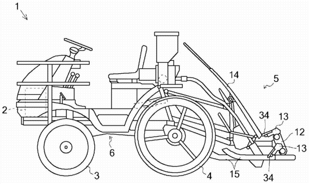
[0044] The rice transplanter 1 will be described with reference to the drawings.

[0045] The rice transplanter 1 uses the power of the engine 2 to drive the front wheels 3 and the rear wheels 4 to travel, and uses the planting unit 5 to perform planting work. The power from the engine 2 is transmitted to the front wheel 3 and the rear wheel 4 via the gearbox 6 , and is transmitted to the planting unit 5 via the gearbox 6 and the inter-plant distance changing device 9 .

[0046] The planting part 5 is equipped with the planting center box 10, the planting helical gear box 11, the rotation box 12, the planting arm 13, the seedling carrying platform 14, and the some float 15.

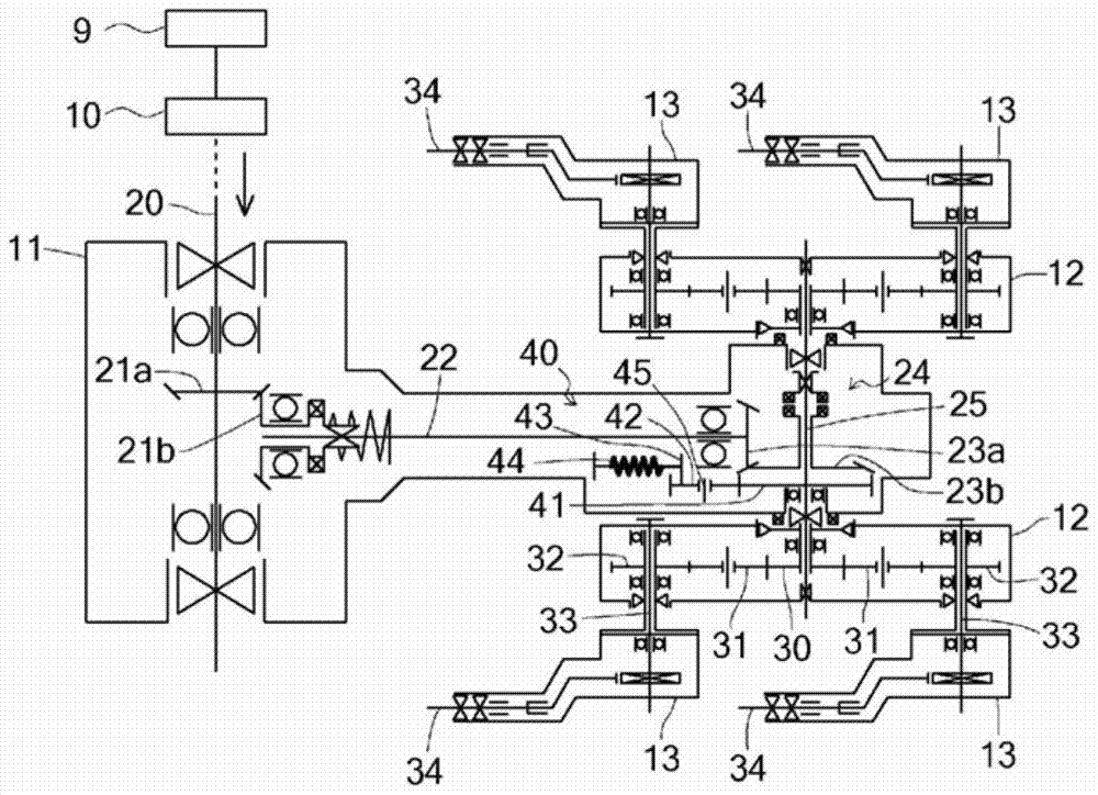
[0047] figure 2 It is a transmission system diagram related to the planting drive of the planting unit 5 . figure 2 One implanting unit is shown, but the other implanting units are constructed in the same way.

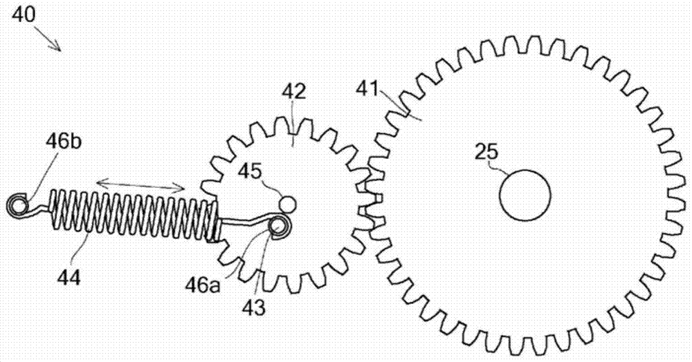
[0048] The power is transmitted from the planting horizontal axis 20 branched from the pl...


PUM


Abstract

The present invention provides a rice transplanter that applies torque that cancels torque fluctuations generated in a planting arm shaft to equalize torque fluctuations and improve phase deviation, thereby rationalizing the trajectory of planting claws and preventing poor planting. This rice transplanter transmits power to the planting arm shaft supporting the rotary box through a non-uniform speed mechanism, and is provided with a torque equalization mechanism that imparts a torque that cancels torque fluctuations generated by the above-mentioned non-uniform speed mechanism, and the above-mentioned The torque equalization mechanism is installed on the above-mentioned implanting arm shaft.

Description

technical field [0001] The present invention relates to a rice transplanter that transmits power to a planting arm via a non-uniform velocity mechanism. Background technique [0002] In the existing rice transplanter, if the trajectory of the front end of the planting claw near the bottom dead center is set to be approximately vertical on the basis of close planting, the speed at which the planting claw leaves the field will be slow in the sparse planting state, so it is easy to The phenomenon of pushing the planted seedlings forward. Conversely, if the trajectory of the front end of the planting claw is set to be approximately vertical near the bottom dead center based on sparse planting, then in the state of close planting, the planting claw will retreat while maintaining the state of entering the field, which is easy to cause The seedlings are scattered and the soil is excavated to produce floating seedlings. [0003] Therefore, there is the following method: based on t...

Claims


Application Information

Patent Timeline
29 Sep 2017
Publication
CN105072885B
IPC
A01C11/02
CPC
A01C19/00; A01C11/003
Inventors
竹山智洋; 土井邦夫