Linear type cutting and suturing device with inter-bridge structure

A bridge structure, linear technology, applied in the field of medical devices, can solve the problems of cumbersome and increased operation time, and achieve the effect of simplifying the operation

Active Publication Date: 2015-12-02
胡振东 +1
View PDF5 Cites 8 Cited by
  • Summary
  • Abstract
  • Description
  • Claims
  • Application Information

AI Technical Summary

Problems solved by technology

But in the end, manual operation to close the residual part is still cumbersome, and the operation time will increase by 20 minutes compared with the traditional end-to-end anastomosis

Method used


Image

  • Linear type cutting and suturing device with inter-bridge structure
  • Linear type cutting and suturing device with inter-bridge structure
  • Linear type cutting and suturing device with inter-bridge structure

Examples


Embodiment 1

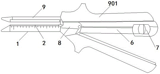
[0033] Embodiment 1: as Figure 1~5 with Figure 8 As shown, the linear cutter and stapler with a bridge structure includes a staple cartridge seat 1, a staple cartridge 2, a cutting knife 3, a sliding knife rail 4, and an anvil 9; the staple cartridge 2 is installed on the staple cartridge seat 1, The nail anvil 9 is detachably connected to the magazine base 1; the magazine base 1 is provided with a sliding knife rail 4 along the central axis direction, and the staple magazine 2 is provided with a sliding knife groove 201 along the central axis direction at the corresponding position of the sliding knife rail 4 , and the sliding knife groove 201 and the staple bin 2 form two spaces; the cutting knife 3 is installed in the sliding knife rail 4, the front end of the cutting knife 3 has a cutting part 301, the cutting knife 3 slides along the sliding knife rail 4, and the sliding knife rail 4 The bottom of the front end is provided with a spacer 401, and the bottom of the front...

Embodiment 2

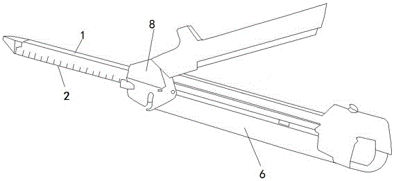
[0035] Embodiment 2: as Figure 6~7 As shown, the difference between the linear cutting stapler with bridge structure and Embodiment 1 is that the rear end of the nail anvil 2 has a groove 902, specifically, the linear cutter stapler with bridge structure includes staples Cartridge 1, staple cartridge 2, cutting knife 3 and sliding knife rail 4, staple cartridge 2 is installed on staple cartridge seat 1, staple cartridge seat 1 is provided with sliding knife rail 4 along the central axis direction, staple cartridge 2 is on the sliding knife rail The corresponding position of 4 is provided with a sliding knife groove 201 along the central axis direction, and the sliding knife groove 201 and the staple bin 2 form two spaces; the cutting knife 3 is installed in the sliding knife rail 4, and the front end of the cutting knife 3 has a cutting part 301 for cutting Knife 3 is movably connected with sliding knife rail 4, and cutting knife 3 can slide in sliding knife rail 4, and the r...

Embodiment 3

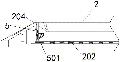
[0037] Embodiment 3: as Figure 8~9 As shown, the linear cutting stapler of the bridge structure includes a staple cartridge seat 1, a staple cartridge 2, a cutting knife 3 and a sliding knife rail 4, and the staple cartridge 2 is installed on the On the staple cartridge holder 1, the staple cartridge holder 1 is provided with a sliding knife rail 4 along the central axis direction, and the staple cartridge 2 is provided with a sliding knife groove 201 along the central axis direction at the corresponding position of the sliding knife rail 4, and the sliding knife groove 201 and the nail The warehouse 2 forms two spaces; a cutting knife 3 is installed in the sliding knife rail 4, and the front end of the cutting knife 3 has a cutting part 301. The cutting knife 3 and the sliding knife rail 4 are movably connected, and the cutting knife 3 can slide in the sliding knife rail 4 The surface of the rear end of the sliding knife groove 201 is also provided with a partition 205, and ...


PUM


Abstract

The invention relates to a linear type cutting and suturing device with an inter-bridge structure. The linear type cutting and suturing device comprises a nail abutting device, a nail bin, a nail bin seat, a cutting knife and a sliding knife rail; the nail abutting device is aligned with the nail bin in an assisting mode to form a nail, the nail bin is installed on the nail bin seat, and the cutting knife is installed on the position, located at the back central axis, of the sliding knife rail; when the cutting knife moves ahead and enters the nail bin along the sliding knife rail, a sliding knife groove is reserved at the central axis of the nail bin; the cutting knife slides ahead on the sliding knife rail, enters the sliding knife groove of the nail bin and arrives at the front end, and a cutting portion is exposed to perform cutting and suturing. According to the linear type cutting and suturing device with the inter-bridge structure, suturing and cutting are synchronously completed, front end cutting and two-side suturing can be achieved, an anastomotic stoma is in a linear shape, and the inter-bridge type is in the mode that the cutting and suturing position only occurs at the front end of the action tissue, and the back end is kept complete.

Description

technical field [0001] The invention relates to the field of medical instruments, in particular to a linear cutting and stapler with bridge structure for operation. Background technique [0002] Esophagogastric "side-to-side anastomosis" is a new type of anastomosis recently developed at home and abroad. Many literatures have reported that its anti-stenosis, anti-reflux and anti-anastomotic leakage characteristics are significantly better than the current routinely used end-to-end anastomosis. In 2009, it was included in the "American General Thoracic Surgery" textbook, which is known as the "Bible", and is now the mainstream anastomosis method for esophageal cancer surgery in the United States. In this operation, after the esophagus is severed, a linear cutting stapler is inserted into the cavity made on the esophageal stump and the gastric tube, and the esophagus and the anterior wall of the gastric tube are first linearly anastomosed laterally, and then the remaining esop...

Claims


Application Information

Patent Timeline
Patent Type & Authority Applications(China)
IPC IPC(8): A61B17/072
CPCA61B17/07207A61B2017/320052
Inventor 胡振东
Owner 胡振东
Why Eureka
Try Eureka