Automatic transmission mechanism for cylindrical workpieces

An automatic transfer, cylindrical technology, used in conveyors, transportation and packaging, etc., can solve the problems of low transfer efficiency, easy rolling of cylindrical workpieces, etc., and achieve the effects of accurate transfer, simple structure and energy saving.

Active Publication Date: 2015-12-02
重庆攸遂科技有限公司
View PDF5 Cites 4 Cited by
  • Summary
  • Abstract
  • Description
  • Claims
  • Application Information

AI Technical Summary

Problems solved by technology

[0004] The present invention intends to provide an automatic transfer mechanism for cylindrical workpieces to solve the problem that cylindrical workpieces tend to roll on the existing transfer mechanism and the transfer efficiency is low

Method used


Image

  • Automatic transmission mechanism for cylindrical workpieces

Examples


Embodiment Construction

[0017] The present invention will be described in further detail below by means of specific embodiments:

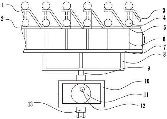
[0018] The reference signs in the drawings of the description include: first platform 1, second platform 2, slant plate 3, cylindrical workpiece 4, lifting plate 5, connecting rod 6, support plate 7, bracket 8, push rod 9, rectangular frame 10, cam 11, rotating shaft 12, guide sleeve 13.

[0019] Such as figure 1 As shown, the automatic transfer mechanism for cylindrical workpieces includes a first platform 1 and a second platform 2 with holes in corresponding positions in the vertical direction, the first platform 1 is located directly above the second platform 2, and the first platform 1 is clamped with the second platform 2 through the slanting plate 3 slanting downward. The shape of the lifting plate 5 matches the holes on the first platform 1 and the second platform 2 , and the lifting plate 5 can be fitted on the first platform 1 and the second platform 2 respecti...


PUM


Abstract

The invention discloses an automatic transmission mechanism for cylindrical workpieces, and relates to the field of transmission mechanisms. The automatic transmission mechanism for the cylindrical workpieces comprises a first platform, a second platform, inclined plates, lifting plates and a driving mechanism; the first platform and the second platform are vertically arranged, the inclined plates are used for connecting the first platform with the second platform, the lifting plates can ascend and descend between the first platform and the second platform, and the driving mechanism pushes the lifting plates to vertically move; holes are formed in the corresponding positions of the first platform and the second platform, and the lifting plates are matched with the holes in shape; and the inclined plates are connected between two adjacent holes of the first platform and the second platform. The automatic transmission mechanism is simple in structure and high in transmission efficiency.

Description

technical field [0001] The invention relates to a transmission mechanism, in particular to an automatic transmission mechanism for cylindrical workpieces. Background technique [0002] In factories, in order to improve production efficiency, assembly line operations are basically adopted. For the processing of many cylindrical workpieces, the assembly line operation of multiple stations is also used. Generally, each station performs fixed engraving, cleaning or spraying operations, and the cylindrical workpieces are processed after the assembly line operation is completed. [0003] Now there is no transfer mechanism specially used to transfer cylindrical workpieces, and ordinary belt drives are still used to transfer cylindrical workpieces. Because the end face of the cylindrical workpiece is circular, if the cylindrical workpiece is placed on the conveyor belt, because the friction force generated by the cylindrical workpiece is small, it may produce relative motion with t...

Claims


Application Information

Patent Timeline
Patent Type & Authority Applications(China)
IPC IPC(8): B65G25/02
Inventor 王树尧
Owner 重庆攸遂科技有限公司
Why Eureka
Try Eureka