Automatic control method of plunger gas-lift liquid drainage production of oil-gas well

An oil and gas well and plunger technology, which is applied in the field of automatic control of the production of oil and gas well plunger gas lift and drainage, can solve the problems of limited application area, incompatibility between plunger gas lift drainage and oil and gas wells, etc. management effect

Inactive Publication Date: 2016-01-13
PETROCHINA CO LTD
View PDF5 Cites 15 Cited by
  • Summary
  • Abstract
  • Description
  • Claims
  • Application Information

AI Technical Summary

Problems solved by technology

[0006] The purpose of the present invention is to overcome the problem that the existing plunger gas-lift liquid discharg

Method used


Image

  • Automatic control method of plunger gas-lift liquid drainage production of oil-gas well
  • Automatic control method of plunger gas-lift liquid drainage production of oil-gas well
  • Automatic control method of plunger gas-lift liquid drainage production of oil-gas well

Examples


Embodiment 1

[0020] In order to overcome the problem that the existing plunger gas lift drainage is not closely combined with the actual liquid accumulation of oil and gas wells and has limited application, this embodiment provides an automatic control method for the production of oil and gas well plunger gas lift drainage, including Follow the steps below:

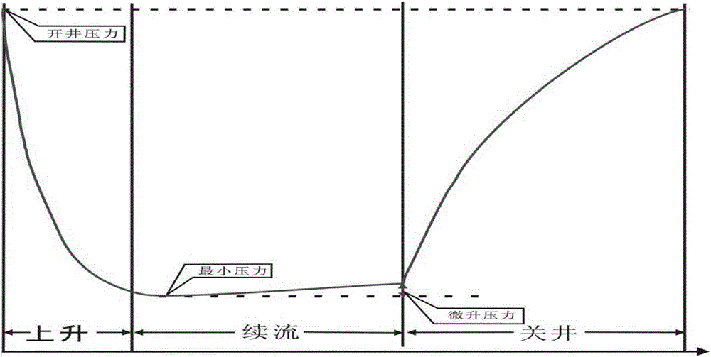
[0021] 1) Open the well, then lower the buffer holder and plunger into the oil and gas well tubing sequentially, connect the blowout preventer at the top of the wellhead Christmas tree or the wellhead Christmas tree, and the plunger is between the buffer holder and the blowout preventer At the same time, a pneumatic membrane valve is installed between the surface pipeline and the blowout preventer to control the switch of the oil and gas well. The pneumatic membrane valve is connected to the plunger controller by the wire, and the plunger controller realizes the operation of the oil and gas well switch by controlling the switch of the ...

Embodiment 2

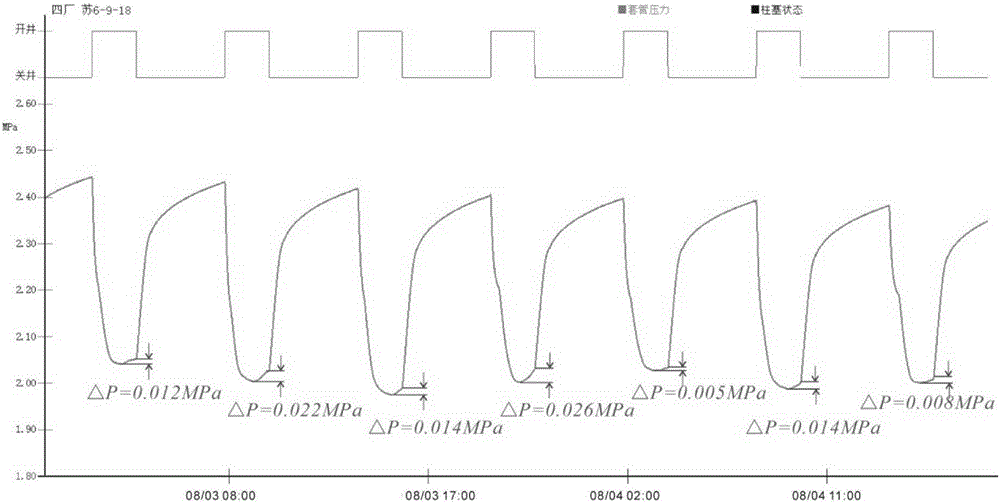
[0033] On the basis of Example 1, in this embodiment, by observing the pressure micro-rise value at the time of shutting down the well, when the plunger controller is set to the pressure micro-rise optimization mode, the opening pressure is 2.4MPa, and the micro-rise pressure is set to 0.015MPa.

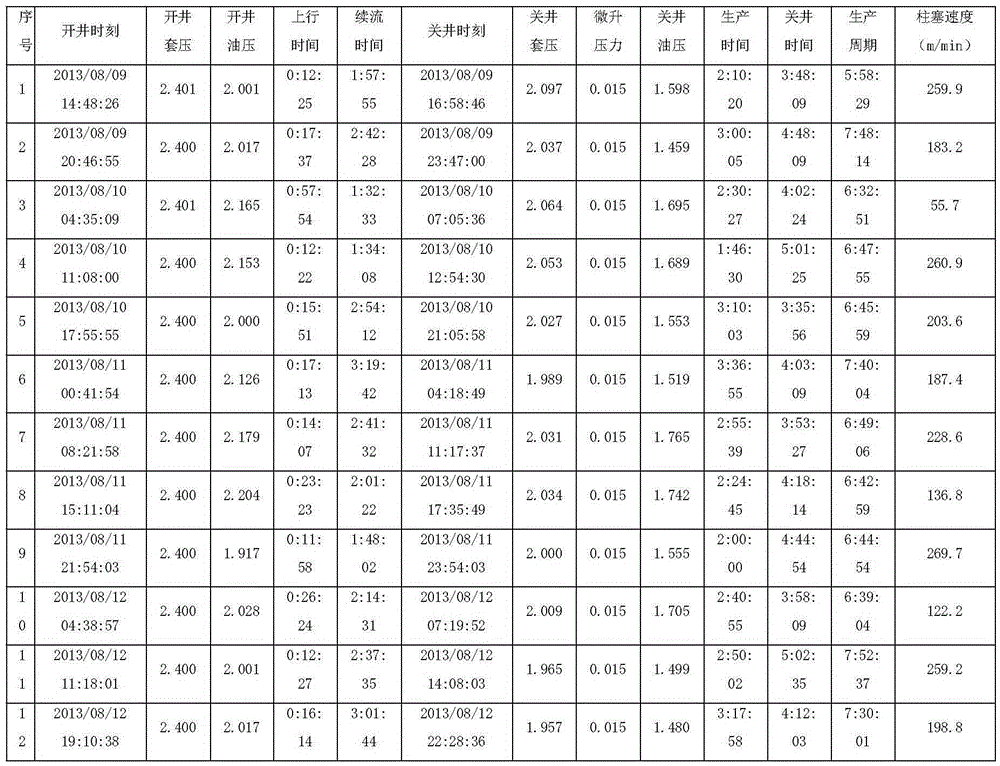
[0034] After the setting is completed, it will start to run, and after the plunger gas lift control system has been in operation for 3 days, export the production report data stored in the plunger controller, as shown in Table 1.

[0035] Table 1:

[0036]

[0037] It can be seen from Table 1 that the casing pressure at the start-up time is 2.4MPa, meeting the preset well-opening conditions; the casing pressure slight rise at the time of well-shut-in is 0.015MPa, meeting the preset well-shut-in conditions. In this mode, the controller automatically adjusts the opening and closing time according to the change of casing pressure, and the production system is in the state of automati...


PUM


Abstract

The invention discloses an automatic control method of plunger gas-lift liquid drainage production of an oil-gas well. The automatic control method includes that a buffering clamping and fixing device and a plunger are lowered into an oil pipe after drifting, a gas production tree of the oil-gas well is connected with a blowout preventing pipe, a pneumatic membrane valve is arranged between a ground pipeline and the blowout preventing pipe and electrically connected with a plunger controller, the plunger controller realizes opening and closing of the gas well by controlling opening and closing of the pneumatic membrane valve, and a pressure sensor is arranged in a wellhead gas production chamber and electrically connected with the plunger controller; a casing pressure value when the plunger controller controls the oil-gas well to be open is set, a casing pressure value when the plunger controller controls the oil-gas well to be closed is set, the plunger controller receives casing pressure value signals measured by the pressure sensor, and opening and closing of the oil-gas well are controlled according to set well opening and closing conditions of the oil-gas well. Well opening or well closing of the oil-gas well is controlled according to changing circumstance of wellhead casing pressure and oil pressure of the oil-gas well, the changing circumstance is closely combined with liquid accumulating circumstance of the oil-gas well, optimal liquid lift quantity is guaranteed, and automated control management of the process of plunger gas-lift liquid drainage gas production is realized.

Description

technical field [0001] The invention belongs to the technical field of oil and gas recovery in oil and gas fields, and in particular relates to an automatic control method for oil and gas well plunger gas lift and liquid discharge production. Background technique [0002] The plunger gas lift liquid drainage process is a technical method that uses the energy of the gas well itself to discharge the liquid out of the wellbore. This technology uses the plunger as the mechanical interface between gas and liquid, uses the gas produced by the gas well to push the plunger to move up and down periodically in the tubing, and then periodically lifts the liquid produced in the formation to the ground, and Produce gas. As a plunger at the gas-liquid interface, it can effectively prevent the gas from going up and the liquid from falling back, reduce the "slipping" effect of the liquid from the bottom of the well to the wellhead, and greatly improve the efficiency of the gas to lift the ...

Claims


Application Information

Patent Timeline
IPC IPC(8): E21B43/00
Inventor 韩强辉慕立俊付钢旦刘双全田伟李耀德李旭日惠艳妮卫亚明肖述琴
Owner PETROCHINA CO LTD
Why Eureka
Try Eureka