Supporting and hoisting mechanism provided with sensor and used for mixing head in foaming machine

A mixing head and foaming machine technology, applied in the field of supporting and hoisting mechanisms, can solve the problems of difficult parameters such as temperature and pressure of polyurethane foaming raw materials, time-consuming and laborious, and increased production costs, so as to reduce production costs, improve production quality, and increase production costs. The effect of production efficiency

Inactive Publication Date: 2016-02-24
张家港力勤机械有限公司
View PDF8 Cites 1 Cited by
  • Summary
  • Abstract
  • Description
  • Claims
  • Application Information

AI Technical Summary

Problems solved by technology

The supporting and hoisting mechanism of the mixing head in the traditional polyurethane foaming machine has the following defects: 1. After the component conveying hard pipe is fixedly installed on the support frame, the pouring height of the mixing head is fixed. When the pouring height needs to be adjusted during the production process, it needs to The mixing head can be adjusted to the position corresponding to the required pouring height only by replacing the component conveying hard pipe of the corresponding length, which not only takes time and effort, but also increases the production cost; The barrel to the mixing head needs to go through a long section of tube, which makes the parameters of the polyurethane foaming raw material in the mixing head, such as temperature and pressure, different from those in the polyurethane foaming raw material barrel, resulting in the polyurethane foaming raw material in the mixing head Parameters such as temperature and pressure are difficult to be grasped in a timely and accurate manner

Method used


Image

  • Supporting and hoisting mechanism provided with sensor and used for mixing head in foaming machine

Examples


Embodiment Construction

[0012] The present invention will be further described in detail below in conjunction with the accompanying drawings and preferred embodiments.

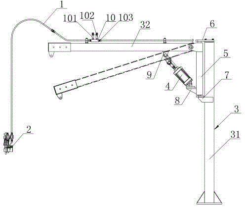
[0013] like figure 1 As shown, the supporting and hoisting mechanism of the mixing head in the foaming machine with sensors includes: a component delivery hard tube 1 that is fixedly connected to the mixing head 2 at one end and communicated with the polyurethane foam raw material barrel at the other end, and the component delivery hard tube 1. It is fixedly installed on the support frame 3. The structure of the support frame 3 includes: a support column 31 and a support boom 32. The inner end of the support boom 32 is hinged on the support column 31. The arm 32 is set and fixedly mounted on the support arm 32, so that the mixing head 2 is supported and hoisted on the outside of the support arm 32, and the support column 31 is hinged with a cylinder 4, and the piston rod of the cylinder 4 is hinged to the support arm 32. Connection,...


PUM


Abstract

The invention discloses a supporting and hoisting mechanism provided with a sensor and used for a mixing head in a foaming machine. The supporting and hoisting mechanism comprises a hard component conveying pipe installed on a supporting frame. The inner end of a supporting suspension arm of the supporting frame is hinged to a supporting stand column of the supporting frame. The hard component conveying pipe is arranged along the supporting suspension arm and is fixedly installed on the supporting suspension arm, and therefore the mixing head is supported and hoisted on the outer side of the supporting suspension arm. A piston rod of an air cylinder on the supporting stand column is hinged to the supporting suspension arm, can drive the outer end of the supporting suspension arm to rotate downwards when retracting inwards and can drive the outer end of the supporting suspension arm to rotate upwards until the supporting suspension arm is located horizontally when stretching outwards; a temperature sensor is installed on an installation pipe of the hard component conveying pipe; the supporting stand column is provided with a rotating mechanism. The supporting and hoisting mechanism has the advantages that the pouring height and the horizontal position of the mixing head can be conveniently adjusted, and the temperature of polyurethane foaming material in the mixing head can be accurately obtained.

Description

technical field [0001] The invention relates to the technical field of polyurethane foam production equipment, in particular to a supporting and hoisting mechanism for a mixing head in a high-pressure polyurethane foaming machine. Background technique [0002] The function of the mixing head in the polyurethane foam machine is to pour the polyurethane foam raw material into the mold. The mixing head is connected with a component conveying hard pipe connected to the polyurethane foam raw material barrel. The supporting and hoisting mechanism of the mixing head in a traditional polyurethane foaming machine includes: a support frame, and the component conveying hard pipe is fixedly installed on the support frame so that Hang the mixing head support above the mold outside the support frame. The supporting and hoisting mechanism of the mixing head in the traditional polyurethane foaming machine has the following defects: 1. After the component conveying hard pipe is fixedly inst...

Claims


Application Information

Patent Timeline
Patent Type & Authority Applications(China)
IPC IPC(8): B29C44/40B29C44/60
CPCB29C44/40B29C44/60
Inventor 王汉力
Owner 张家港力勤机械有限公司
Why Eureka
Try Eureka