Self-balancing electric brush

An electric brush and self-balancing technology, applied in the field of brushes, can solve the problems of displacement, affecting the washing effect, and the brush head is not easy to control, so as to achieve the effect of easy control

Active Publication Date: 2017-10-20
梁大君 +1
View PDF12 Cites 0 Cited by
  • Summary
  • Abstract
  • Description
  • Claims
  • Application Information

AI Technical Summary

Problems solved by technology

At present, most electric brushes use a single cylindrical washing brush head to rotate to scrub the items. When washing, the items will slide uncontrollably with the rotation of the brush head, resulting in displacement. At the same time, the items will also give the brush head a reaction force, making the brush head difficult to control
In addition, when using this electric brush to wash items, the surface of the items is also easy to wrinkle and knot, which affects the washing effect

Method used


Image

  • Self-balancing electric brush
  • Self-balancing electric brush
  • Self-balancing electric brush

Examples


Embodiment 1

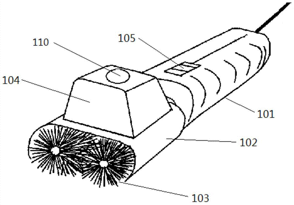
[0058] Example 1, such as Figure 1-Figure 3 as shown,

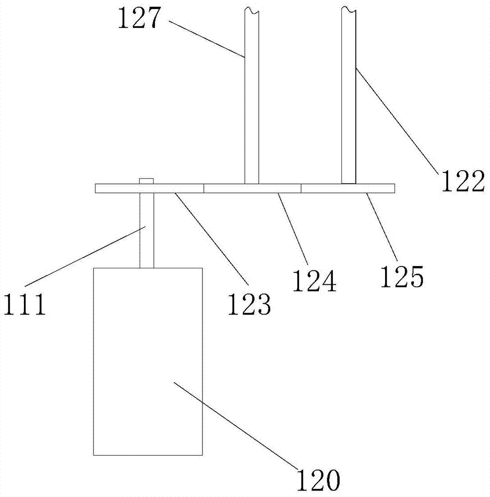
[0059] The self-balancing electric brush includes a handle 101, a power unit 120 and at least one brush head group 103, the power unit 120 is arranged in the handle 101, the output shaft 111 of the power unit 120 is connected with the brush head group 103, and the brush head group 103 is included in the working When rotating the first brush head 126 and the second brush head 128 in opposite directions. The power unit 120 includes a transmission device connected to the output shaft 111. The transmission device includes a turntable 123, a first gear 124, a second gear 125, a first shaft 122 and a second shaft 127. The turntable 123 is connected to the output shaft 111 and is connected to the first The gears 124 mesh with each other, the second gear 125 and the first gear 124 mesh with each other, the first gear 124 and the second gear 125 are fixedly connected axially to the first rotating shaft 122 and the second rotatin...

Embodiment 2

[0061] Example 2, such as Figure 4-Figure 6 as shown,

[0062] The self-balancing electric brush includes a handle 101, a power unit 120 and at least one brush head group 103, the power unit 120 is arranged in the handle 101, the output shaft 111 of the power unit 120 is connected with the brush head group 103, and the brush head group 103 is included in the working When rotating the first brush head 126 and the second brush head 128 in opposite directions. The power unit 120 includes a first power unit and a second power unit, and both the first power unit and the second power unit are connected with a reduction gearbox 121, and the first brush head 126 and the second brush head 128 are sleeved on the first power unit respectively. On the output shaft 111 of the reduction gearbox 121 of the device and the output shaft 111 of the reduction gearbox 121 of the second power plant.

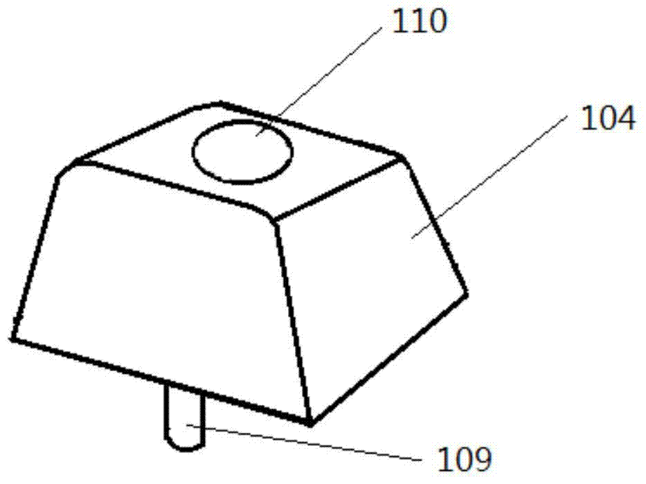
[0063] The self-balancing electric brush also includes a lotion box 104 , the bottom of the lot...


PUM


Abstract

The invention provides a self-balancing electric brush. The self-balancing electric brush comprises a handle, a power device and at least one brush head group, wherein the power device is arranged in the handle, an output shaft of the power device is connected with the at least one brush head group, and the at least one brush head group comprises a first brush head and second brush head with different rotation directions during work. When the electric brush with the structure is used, the at least one brush head group contacts the objects needing to be brushed and washed, such as clothes, shoes and cars, and generates two drawing forces having different directions on the surfaces of the objects; if the self-balancing electric brush is used for washing clothes, the phenomenon that the clothes shrink to form a ball due to sliding so that the washing effect is affected is effectively avoided. When the self-balancing electric brush is used for washing objects, the handle is subjected to two counter-acting forces from the objects, and the two counter-acting forces counteract mutually due to different directions, so that the brush heads are kept balanced, and are easy to operate and control.

Description

technical field [0001] The invention relates to the field of brushes, in particular to a self-balancing electric brush. Background technique [0002] The existing electric brush comprises a handle and a brush head, and a motor for controlling the rotation of the brush head is arranged in the handle. At present, most electric brushes use a single cylindrical washing brush head to rotate to scrub the items. When washing, the items will slide uncontrollably with the rotation of the brush head, resulting in displacement. At the same time, the items will also give the brush head a reaction force, making the brush head Not easy to control. In addition, when using this electric brush to wash items, the surface of the items is also prone to wrinkling and knotting, which affects the washing effect. Contents of the invention [0003] The present invention provides a self-balancing electric brush, aiming to improve the above problems. [0004] The present invention is achieved lik...

Claims


Application Information

Patent Timeline
Patent Type & Authority Patents(China)
IPC IPC(8): A46B13/02
CPCA46B13/02A46B2200/3046A46B2200/3053A46B2200/306
Inventor 梁大君梁韵高小明
Owner 梁大君
Why Eureka
Try Eureka