
Installing and locking assembly applicable to circuit board and flexible to move
A technology for installing components and locking components, applied in metal processing, metal processing equipment, manufacturing tools, etc., can solve the problems of increased circuit board production costs, extra space costs, inconvenient centralized storage and transportation, etc.
- Summary
- Abstract
- Description
- Claims
- Application Information
AI Technical Summary
Problems solved by technology
Method used
Image

Examples
Embodiment Construction
[0009] Combine below figure 1 The present invention will be described in detail.
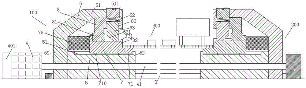
[0010] According to an embodiment, a flexible mounting and locking assembly for a circuit board 300 includes a drive motor 4 fixedly connected to the base frame, a drive screw 41 power-coupled with the drive motor 4 , and a drive screw 41 mounted on the drive screw 41 The left mounting assembly 100 and the right mounting assembly 200 are respectively driven by two sections of threads with opposite directions of rotation, and the guide rail 3 is fixedly connected with the base frame and guides the left mounting assembly 100 and the right mounting assembly 200, wherein , the left mounting assembly 100 and the right mounting assembly 200 are symmetrically arranged left and right, and each includes: a threaded base 5 threaded with the drive screw 41, and a fixing frame 6 fixedly connected to the outer end of the threaded base 5 , a slidable installation bearing block 7 in the guide rail groove 51 o...
PUM
 Abstract
Description
Claims
Application Information