Control system of mounting and locking device for circuit board

A locking device and control system technology, which is applied in manufacturing tools, metal processing, metal processing equipment, etc., can solve the problems of increasing the production cost of circuit boards, inconvenient centralized storage and transportation, and extra space costs, etc.

Inactive Publication Date: 2016-03-23
方德兰
View PDF6 Cites 0 Cited by
  • Summary
  • Abstract
  • Description
  • Claims
  • Application Information

AI Technical Summary

Problems solved by technology

However, this method significantly increases the production cost of the circuit board, and the fixed vertical feet are likely to cause additional space costs in transportation and storage, which is not convenient for centralized storage and transportation.

Method used


Image

  • Control system of mounting and locking device for circuit board
  • Control system of mounting and locking device for circuit board

Examples


Embodiment Construction

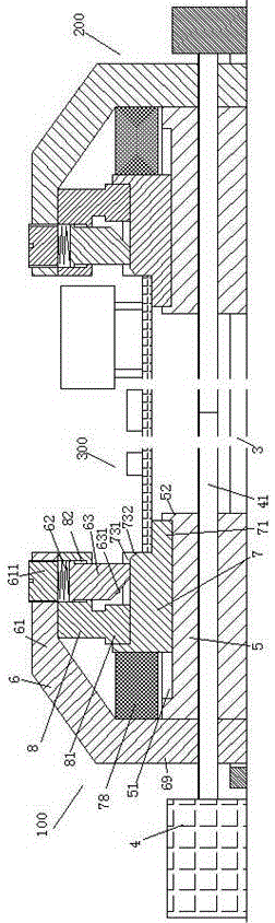
[0010] Combine below Figure 1-2 The present invention will be described in detail.

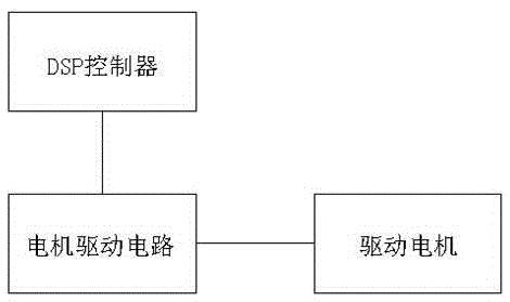
[0011] According to an embodiment, a control system for installing and locking a circuit board 300 includes a DSP controller, a motor drive circuit, a drive motor 4 fixedly connected to the base frame, a drive screw 41 dynamically coupled to the drive motor 4, The left mounting assembly 100 and the right mounting assembly 200 respectively driven by the two sections of screw threads with opposite directions on the driving screw 41 are fixedly connected with the base frame and carry out the operation on the left mounting assembly 100 and the right mounting assembly 200 Guide rail member 3, the DSP controller is electrically connected with the drive motor 4 through a motor drive circuit, so as to control the rotation of the drive motor 4, wherein the left mounting assembly 100 and the right mounting assembly 200 are symmetrically arranged , and each includes: a threaded base 5 threaded with the...


PUM


Abstract

A control system of a mounting and locking device for a circuit board (300) comprises a DSP controller, a motor driving circuit, a driving motor (4), a driving screw (41), a left mounting assembly (100), a right mounting assembly (200) and guide rail parts (3), wherein the driving motor (4) is fixedly connected to a base frame; the driving screw (41) is in power connection with the driving motor (4); the left mounting assembly (100) and the right mounting assembly (200) are correspondingly driven by two threads, opposite in screwing directions, in the driving screw (41); the guide rail parts (3) are fixedly connected to the base frame and are correspondingly used for guiding the left mounting assembly (100) and the right mounting assembly (200); the DSP controller is electrically connected to the driving motor (4) through the motor driving circuit so as to control the rotating of the driving motor (4); the left mounting assembly (100) and the right mounting assembly (200) are symmetrically arranged at left and right.

Description

technical field [0001] The invention relates to the field of circuit boards, in particular to a control system for installation and locking devices of circuit boards. Background technique [0002] The installation and removal of the circuit board will affect the operation stability and reliability of the equipment using the circuit board, and will affect its maintainability. The installation of the current circuit board often adopts the method of opening a hole on the circuit board and inserting the circuit board through the fixing column arranged on the equipment rack. Holds the circuit board in place and can be removed for maintenance during use. [0003] However, this installation mode first needs to open a through hole on the circuit board, which will affect the wiring layout of the circuit board itself, and will also affect the stability of the wiring around the through hole. Second, such vias affect the mechanical strength of the board itself. More importantly, this...

Claims


Application Information

Patent Timeline
IPC IPC(8): B23P19/04
CPCB23P19/04B23P19/006
Inventor 方德兰
Owner 方德兰
Why Eureka
Try Eureka