Top pressing mechanism of winding machine

A technology of winding machine and driving mechanism, which is applied in the directions of function indication, delivery of filamentous materials, thin material handling, etc. It can solve the problems of structural limitations, short service life of products, difficult operation, etc., and achieve simple manufacturing and assembly and long service life , the effect of simple operation

Active Publication Date: 2016-06-15
常州光明包装机械有限公司
View PDF14 Cites 2 Cited by
  • Summary
  • Abstract
  • Description
  • Claims
  • Application Information

AI Technical Summary

Problems solved by technology

[0002] First of all, due to structural limitations, the traditional top pressing mechanism almost always uses assembly and welding to find the center, which is difficult to operate and the alignment effect is not good
[0003] Secondly, the manufacture and assembly of the topping mechanism of the traditional winding machine is cumbersome, and the pressure far exceeds the expected pressure due to jamming, tilting of the pressure action point, misoperation, etc., and the positive pressure generated at the far end is transmitted to the The installation position will generate a large overturning moment on the column, which will cause a large deformation of the bracket itself, especially its pressure detection method. When the surface of the material is seriously inclined, or the shaft and hole are stuck, it will produce a far exceeding The pressure allowed by the design will cause serious accidents such as deformation or breakage of the bracket, broken chain, obvious shaking and deformation of the column, and even column breakage. The service life of the product is short and the reliability is poor.

Method used


Image

  • Top pressing mechanism of winding machine
  • Top pressing mechanism of winding machine
  • Top pressing mechanism of winding machine

Examples


Embodiment Construction

[0027] The present invention will be further described below in conjunction with the accompanying drawings and given embodiments.

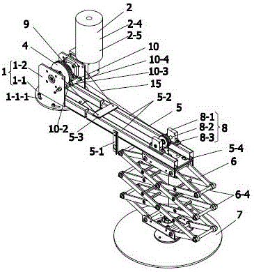
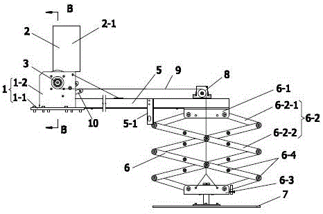
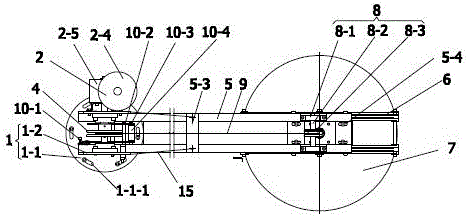
[0028] Such as Figure 1~5 As shown, a topping mechanism of a winding machine has a driving mechanism 2, a bracket 5 and a topping plate 7, and also has a mounting seat 1, a driving mechanism 2, a main shaft 3, a driven wheel 4, a bracket 5, a scissor swing bar 6 and a topping Disk 7, the main shaft 3 is installed on the mounting base 1 and one end is connected with the driving mechanism 2, the driving mechanism 2 can drive the main shaft 3 to rotate, and the driven wheel 4 is fixedly connected to the main shaft 3.

[0029] Such as figure 1 , 2 , 3, and 5, one end of the support 5 is fixedly connected to the mounting base 1, the other end is fixedly connected to the top of the telescopic mechanism 6, and the other end is also equipped with a steering mechanism 8.

[0030] Such as figure 1 , 2 , Shown in 5, the bottom of described telescoping ...


PUM


Abstract

The invention discloses a top pressing mechanism of a winding machine. The top pressing mechanism comprises a drive mechanism, a bracket and a top pressing plate, and further comprises a mounting base, a main shaft, a driven wheel and a telescoping mechanism as well as a traction rope, wherein the main shaft is mounted on the mounting base, and one end of the main shaft is connected to the drive mechanism; the drive mechanism can drive the main shaft to rotate; a driven wheel is fixedly connected on the main shaft; one end of the bracket is fixedly connected to the mounting base; the other end of the bracket is fixedly connected to the upper part of the telescoping mechanism; the other end of the bracket is further provided with a steering mechanism; the lower part of the telescoping mechanism is connected to the top pressing plate; one end of the traction rope is fixedly connected to the main shaft or the driven wheel; and the other end of the traction rope is fixedly connected to the lower part of the telescoping mechanism after being steered along a steering wheel. The top pressing mechanism is simpler to manufacture and assemble, and simpler to operate; self-weight type top pressing is adopted, so that the pressure of the top pressing mechanism is always kept constant and pressure exceeding expectation is not generated, and therefore, the service life of the machine is longer, and the reliability is higher.

Description

technical field [0001] The invention relates to the field of packaging machinery, in particular to a top-pressing mechanism of a winding machine. Background technique [0002] First of all, due to structural limitations, the traditional jacking mechanism almost always uses assembly and welding to find the center, which is difficult to operate and the alignment effect is not good. [0003] Secondly, the manufacture and assembly of the topping mechanism of the traditional winding machine is cumbersome, and the pressure far exceeds the expected pressure due to jamming, tilting of the pressure action point, misoperation, etc., and the positive pressure generated at the far end is transmitted to the The installation position will generate a large overturning moment on the column, which will cause a large deformation of the bracket itself, especially its pressure detection method. When the surface of the material is seriously inclined, or the shaft and hole are stuck, it will prod...

Claims


Application Information

Patent Timeline
Patent Type & Authority Applications(China)
IPC IPC(8): B65H54/72B65H54/74B65H63/00
CPCB65H54/72B65H54/74B65H63/00B65H2515/30B65H2220/02
Inventor 蒋峰严馀
Owner 常州光明包装机械有限公司
Why Eureka
Try Eureka