Power distribution cabinet for electric power equipment

A technology for power equipment and power distribution cabinets, applied in the field of power distribution cabinets, can solve problems such as hidden dangers in operation, easy exposure of contacts, and complicated wiring

Inactive Publication Date: 2016-07-20
尚庆光
View PDF5 Cites 2 Cited by
  • Summary
  • Abstract
  • Description
  • Claims
  • Application Information

AI Technical Summary

Problems solved by technology

In the prior art, some manual power-off methods are often used, which often cause troublesome operation and cause hidden dangers in operation
In some automatic power-off methods, because the contacts are on the door body, the electrical wirin

Method used


Image

  • Power distribution cabinet for electric power equipment
  • Power distribution cabinet for electric power equipment

Examples


Embodiment Construction

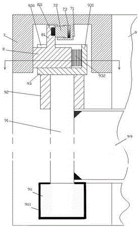
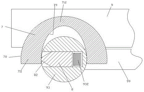
[0008] Combine below Figure 1-2 The present invention will be described in detail.

[0009] According to the embodiment of the present invention, the power distribution cabinet for electric equipment is used for distributing power from the power source to the electric load. The power distribution cabinet device includes a fixed cabinet 9 for installing power distribution devices. The fixed cabinet The upper end of the body 9 is fixedly equipped with a bearing 92, and the lower end of the fixed cabinet body 9 is equipped with a rotating motor 90, and the bearing 92 and the rotating motor 90 are on the same vertical plane, and the output shaft of the rotating motor 90 is fixed A pivot shaft 91 is installed, and the upper end of the pivot shaft 91 is rotatably installed in the bearing member 92. A pivot door 99 is fixedly installed on the pivot shaft 91, and an active electrical device is installed on the pivot door 99. , the rotating motor 90 is used to drive the rotation of t...


PUM


Abstract

The invention relates to a power distribution cabinet for electric power equipment. The power distribution cabinet is used for distributing power from a power source to a power utilization load. The power distribution cabinet comprises a fixed cabinet body (9) for installing a power distribution device; the upper end of the fixed cabinet body (9) is provided with a bearing component (92); the lower end of the fixed cabinet body (9) is provided with a rotating motor (90); the bearing component (92) and the rotating motor (90) are in the same vertical plane; the output shaft of the rotating motor (90) is fixedly provided with a pivoting shaft (91); the upper end of the pivoting shaft (91) is rotatably installed in the bearing component (92); a pivoted door (99) is fixed to the pivoting shaft (91); and the upper end of the pivoting shaft (91) is fixedly provided with a cylindrical cap body (93) which is located on the bearing component (92) and is axially positioned by means of the bearing component (92).

Description

technical field [0001] The invention relates to the field of power distribution, in particular to a power distribution cabinet for power equipment. Background technique [0002] In the field of power distribution, it is often necessary to set up a power distribution cabinet to install various power distribution device components to complete the function of distributing power for various power loads. In the power distribution cabinet, some instrumentation and other devices are often arranged on the cabinet body cover, so as to display various power consumption parameters and operation signals for the operator when the power distribution cabinet is working. This is required to power these devices located on the cabinet lid. In order to ensure the safety of use and device maintenance, it is necessary to cut off the power for these cabinet covers when they are in the open state. In the prior art, some manual power-off methods are often used, which often cause troublesome opera...

Claims


Application Information

Patent Timeline
IPC IPC(8): H02B1/30H01H9/22
CPCH02B1/306H01H9/22
Inventor 尚庆光
Owner 尚庆光
Why Eureka
Try Eureka