Method for monitoring axial force of foundation pit steel support by means of laser distance measuring sensor

A technology of laser distance measurement and steel support, which is applied in the test of basic structure, basic structure engineering, construction, etc. It can solve the problems of many factors affecting the monitoring accuracy, the accuracy is not easy to guarantee, and the installation requirements are high, so that the monitoring operation is simple and fast , reliable monitoring results and high monitoring efficiency

Inactive Publication Date: 2016-08-10
SHAOXING UNIVERSITY
View PDF7 Cites 3 Cited by
  • Summary
  • Abstract
  • Description
  • Claims
  • Application Information

AI Technical Summary

Problems solved by technology

[0003] There are two main methods for monitoring the axial force of the steel support structure of the existing foundation pit engineering: one is to install strain gauges on the steel support, but the installation is more dangerous, and the installation requirements are high. Generally, three or four are installed on one steel support. Strain gauges are expensive, and there are many factors affecting the monitoring accuracy, so the accuracy is not easy to guarantee; the other is to install the axial force gauge in series at the end of the steel support, which is complicated to install, especially the axial force gauge and the steel support are installed in series , the construction unit needs to cooperate to configure the steel support to an appropriate length, and it cannot be implemented if the steel support has been configured or has been constructed

Method used


Image

  • Method for monitoring axial force of foundation pit steel support by means of laser distance measuring sensor
  • Method for monitoring axial force of foundation pit steel support by means of laser distance measuring sensor
  • Method for monitoring axial force of foundation pit steel support by means of laser distance measuring sensor

Examples


Embodiment Construction

[0023] The present invention will be further described below in conjunction with specific examples, but the protection scope of the present invention is not limited thereto.

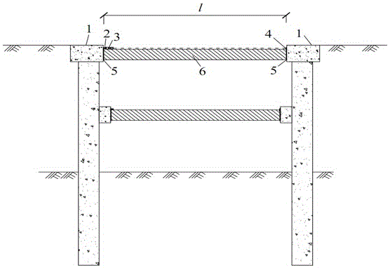
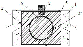
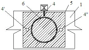
[0024] Such as Figure 1-5 As shown, the present invention uses a laser ranging sensor to monitor the method for the axial force of the foundation pit steel support. The test device used includes a laser ranging sensor 3, a fixing device 2 and a steel backing plate 5, and the steel backing plate 5 is installed on the steel support of the foundation pit. 6, the steel backing plate 5 is provided with a reflector 4, which is welded to the steel backing plate as a point of the steel support deformation measuring line, and the reflector 4 is located on the opposite side of the fixing device 2, and the fixing device 2 and the steel backing The plate 5 is welded as a point of the steel support deformation measuring line. The bottom end of the laser ranging sensor 3 is provided with a threaded hole, and the end ...


PUM


Abstract

The invention relates to a method for monitoring the axial force of a foundation pit steel support by means of a laser distance measuring sensor. The method comprises the following steps that (1), after the foundation pit steel support is erected and before pre-tightening force is applied, a fixing device is welded to a foundation pit steel support end steel base plate on one side, and a reflector is arranged at the corresponding position of a foundation pit steel support steel base plate on the other side; (2), the laser distance measuring sensor and the fixing device are connected, laser points of the laser distance measuring sensor irradiate the center of the reflector to be subjected to point measurement, and then readings are read; and (3), according to the specified measurement frequency, the above measurement steps are repeated, the readings are recorded, the difference between the readings and the measured value of the first time is steel support deformation at various monitoring time points, and the axial force of the steel support can be calculated based on the Hooke's law. According to the method for monitoring the axial force of the foundation pit steel support, the structure is simple, mounting is convenient, operation is fast, and the precision requirement can be met; and the manufacturing cost is low, and application and popularization are easy.

Description

technical field [0001] The invention relates to a monitoring method for monitoring the axial force of foundation pit steel support by using a laser ranging sensor, which is mainly used for monitoring the axial force of foundation pit engineering steel support. Background technique [0002] In the construction of foundation pit engineering, steel support is widely used because of its advantages of easy installation and removal, and low material consumption. The support axial force is the main evaluation index for the safety of foundation pit engineering, so it is the Main monitoring items. [0003] There are two main methods for monitoring the axial force of the steel support structure of the existing foundation pit engineering: one is to install strain gauges on the steel support, but the installation is more dangerous, and the installation requirements are high. Generally, three or four are installed on one steel support. Strain gauges are expensive, and there are many fac...

Claims


Application Information

Patent Timeline
Patent Type & Authority Applications(China)
IPC IPC(8): E02D33/00
CPCE02D33/00
Inventor 夏才初陈忠清杜时贵
Owner SHAOXING UNIVERSITY
Why Eureka
Try Eureka