A double-simply-supported anti-drop comb-toothed bridge telescopic device

A telescopic device and double simply supported technology, applied in bridges, bridge parts, bridge construction, etc., can solve problems affecting waterstops, drops, and short service life, etc., to achieve extended service life, strong shock absorption capacity, and enhanced safety Effect

Inactive Publication Date: 2017-08-25
SHANGHAI HUICHENG ARCHITECTURE DECORATION
View PDF5 Cites 0 Cited by
  • Summary
  • Abstract
  • Description
  • Claims
  • Application Information

AI Technical Summary

Problems solved by technology

The seam-riding expansion device is a single movable comb plate at the seam of the bridge. The comb teeth of the single movable comb plate are locally simply supported. When the force is applied, it is not dispersed within a width of one meter. However, the winding degree of the teeth is greatly increased, and the fatal disadvantage is that the garbage on the bridge surface directly falls into the waterstop from the gap between the comb teeth, which affects the function of the waterstop
[0003] The seam-riding telescopic device of the prior art is stressed by the comb teeth of a single comb tooth plate (movable comb tooth plate) in the bridge seam area, which has defects such as large comb tooth winding degree, low rigidity, and short service life. Garbage is easy to fall directly from the comb gap into the waterstop, affecting the function of the waterstop
Especially for the large-displacement seam-riding comb-shaped bridge expansion device, this phenomenon is more serious and cannot be solved for a long time, which has seriously affected the development of highway and urban viaduct construction in our country

Method used


Image

  • A double-simply-supported anti-drop comb-toothed bridge telescopic device
  • A double-simply-supported anti-drop comb-toothed bridge telescopic device
  • A double-simply-supported anti-drop comb-toothed bridge telescopic device

Examples


Embodiment Construction

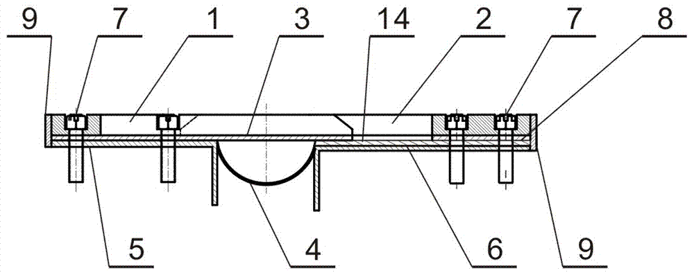
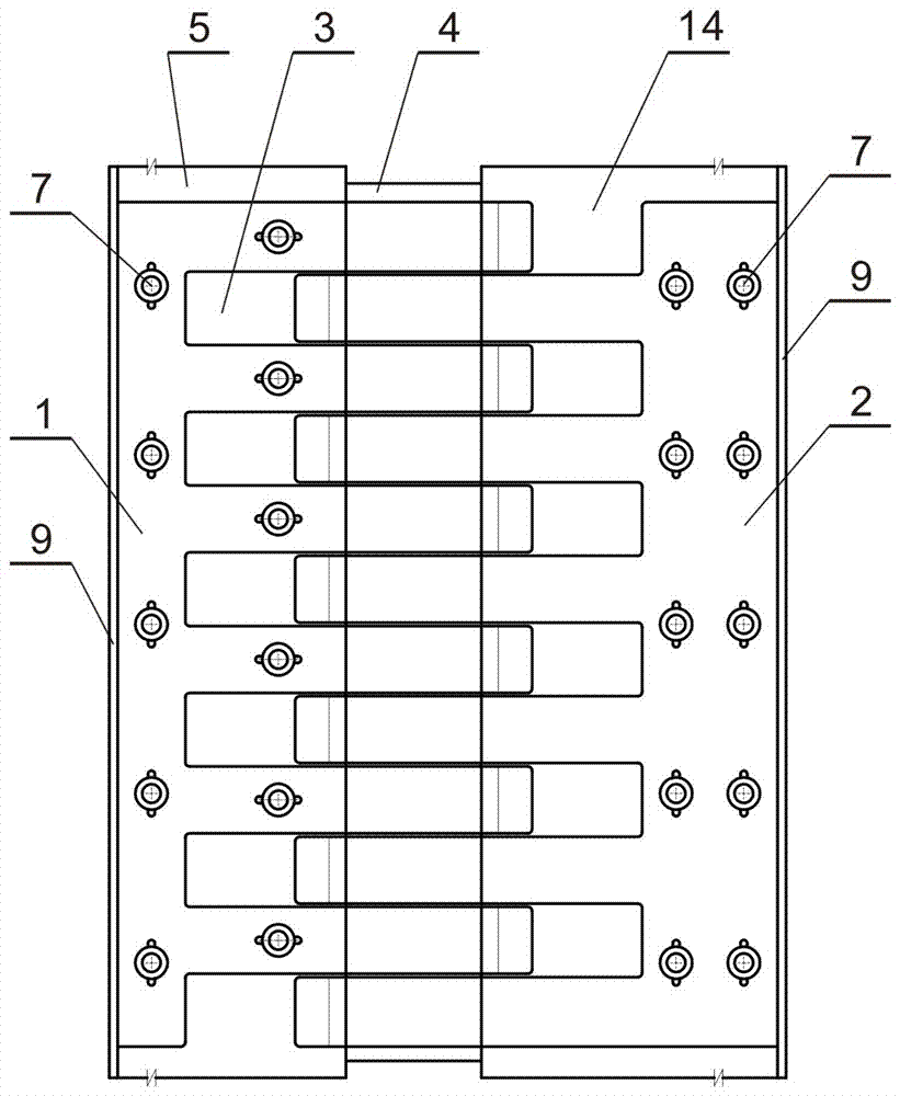
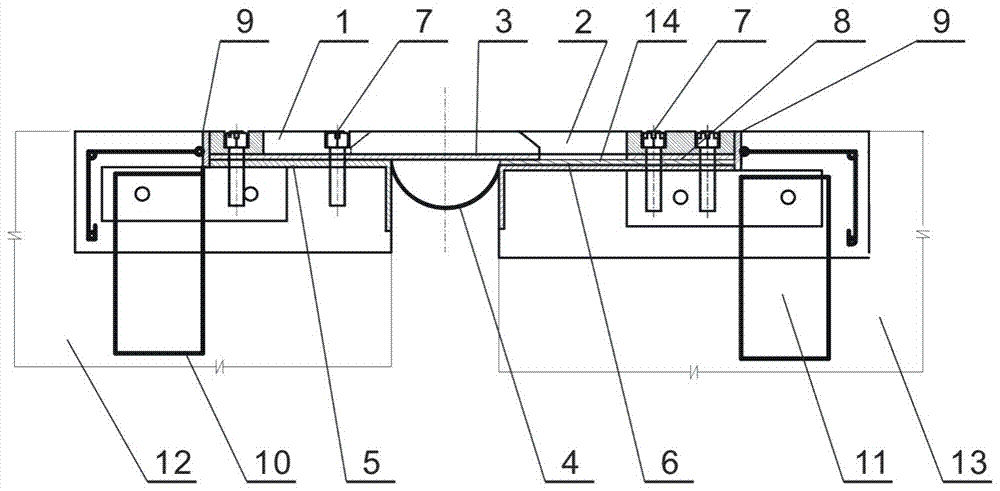
[0014] See attached figure 1 ~ attached figure 2 , The present invention is composed of A comb plate 1, B comb plate 2, anti-drop steel plate 3, rubber waterstop 4, A base anchor 5 and B base anchor 6. The A comb tooth plate 1 is arranged on the anti-drop steel plate 3, the two comb teeth of the B comb tooth plate 2 and the A comb tooth plate 1 are mutually socketed and placed on the anti-drop steel plate 3, and the comb teeth of the B comb tooth plate 2 The comb teeth of the A comb tooth plate 1 and the anti-drop steel plate 3 are slidingly connected; the anti-drop steel plate 3 is supported on the A base anchor 5 and the B base anchor 6 provided with a stainless steel slide plate 14 with a simply supported structure; The tooth root end plate of comb plate A 1 is fixedly connected with anti-falling steel plate 3 and A base anchor 5 by anti-retraction bolt 7. A base anchor 5 is welded and fixed, and is fastened by nuts and stop bolts 7 to fix the root end plate of the A com...


PUM


Abstract

The invention discloses a double-simple-support type anti-falling comb-shaped bridge expansion device. The device is characterized in that a comb plate A is arranged on an anti-falling steel plate, comb teeth of a comb plate B and comb teeth of the comb plate A are arranged on the anti-falling steel plate flat in a mutual insertion mode, and the anti-falling steel plate is supported by a base anchoring part A and a base anchoring part B provided with a stainless steel sliding plate through a simple support structure; a tooth root end plate of the comb plate A is fixedly connected with the anti-falling steel plate and the base anchoring part A; a tooth root end plate of the comb plate B is arranged on the stainless steel sliding plate through a leveling steel plate and fixedly connected with the leveling steel plate, the stainless steel sliding plate and the base anchoring part B. Compared with the prior art, the device has the advantages that comb teeth of the comb plate B and comb teeth of the comb plate A intersect and stressed together in a simple support mode, the winding degree of comb teeth is reduced greatly, the rigidity of comb teeth is improved by 100%, safety performance is improved, service life is prolonged, and the device is especially suitable for high-grade highway bridges, elevated bridges and ultralong flexible bridges.

Description

technical field [0001] The invention relates to a bridge expansion joint device, in particular to a double simply supported anti-drop comb tooth bridge expansion device. Background technique [0002] The national standard JT / T723-2008 unitary multi-directional displacement comb-shaped bridge expansion device recommends two different structures of the comb-shaped bridge expansion device, the saddle type and the cross-slot type. Span-span type telescopic device, solid slabs per meter width simply supported force-bearing slabs have high rigidity and small deflection, and solid slabs per meter width prevent garbage and sundries on the bridge deck from falling into the waterstop. The seam-riding expansion device is a single movable comb plate at the seam of the bridge. The comb teeth of the single movable comb plate are locally simply supported. When the force is applied, it is not dispersed within a width of one meter. However, the degree of tooth winding is greatly increased, ...

Claims


Application Information

Patent Timeline
Patent Type & Authority Patents(China)
IPC IPC(8): E01D19/06
CPCE01D19/06
Inventor 傅若梁黄桂福
Owner SHANGHAI HUICHENG ARCHITECTURE DECORATION
Why Eureka
Try Eureka