Bearing chamber axle center ventilating structure and gas turbine engine with same

A technology of engine and bearing cavity, which is applied in the direction of engine components, engine lubrication, turbine/propulsion device lubrication, etc. It can solve the problems of complex calculation of secondary air system, many uncertain factors in adjustment, engine oil leakage, etc., and achieve Improved economy and environmental friendliness, ease of design and adjustment, and the effect of reducing the amount of lubricating oil

Active Publication Date: 2016-08-17
INST OF ENGINEERING THERMOPHYSICS - CHINESE ACAD OF SCI
View PDF7 Cites 17 Cited by
  • Summary
  • Abstract
  • Description
  • Claims
  • Application Information

AI Technical Summary

Problems solved by technology

In this system, the pressure of the bearing cavity of the cold end part of the engine and the bearing cavity of the hot end part of the engine is maintained by two sets of ventilation systems, and there may be differences in the internal pressure, which makes the calculation of the secondary air system complex and has many uncertain factors in the adjustment, which may easily lead to engine failure. Failures caused by lubricating oil leakage or poor circulation; at the same time, due to the existence of two sets of ventilation systems, the complexity of the engine structure and design is increased

Method used


Image

  • Bearing chamber axle center ventilating structure and gas turbine engine with same
  • Bearing chamber axle center ventilating structure and gas turbine engine with same
  • Bearing chamber axle center ventilating structure and gas turbine engine with same

Examples


Embodiment Construction

[0021] In order to make the object, technical solution and advantages of the present invention clearer, the present invention will be further described in detail below with reference to the accompanying drawings and examples. It should be noted that the following descriptions are only preferred embodiments of the present invention, and therefore do not limit the protection scope of the present invention.

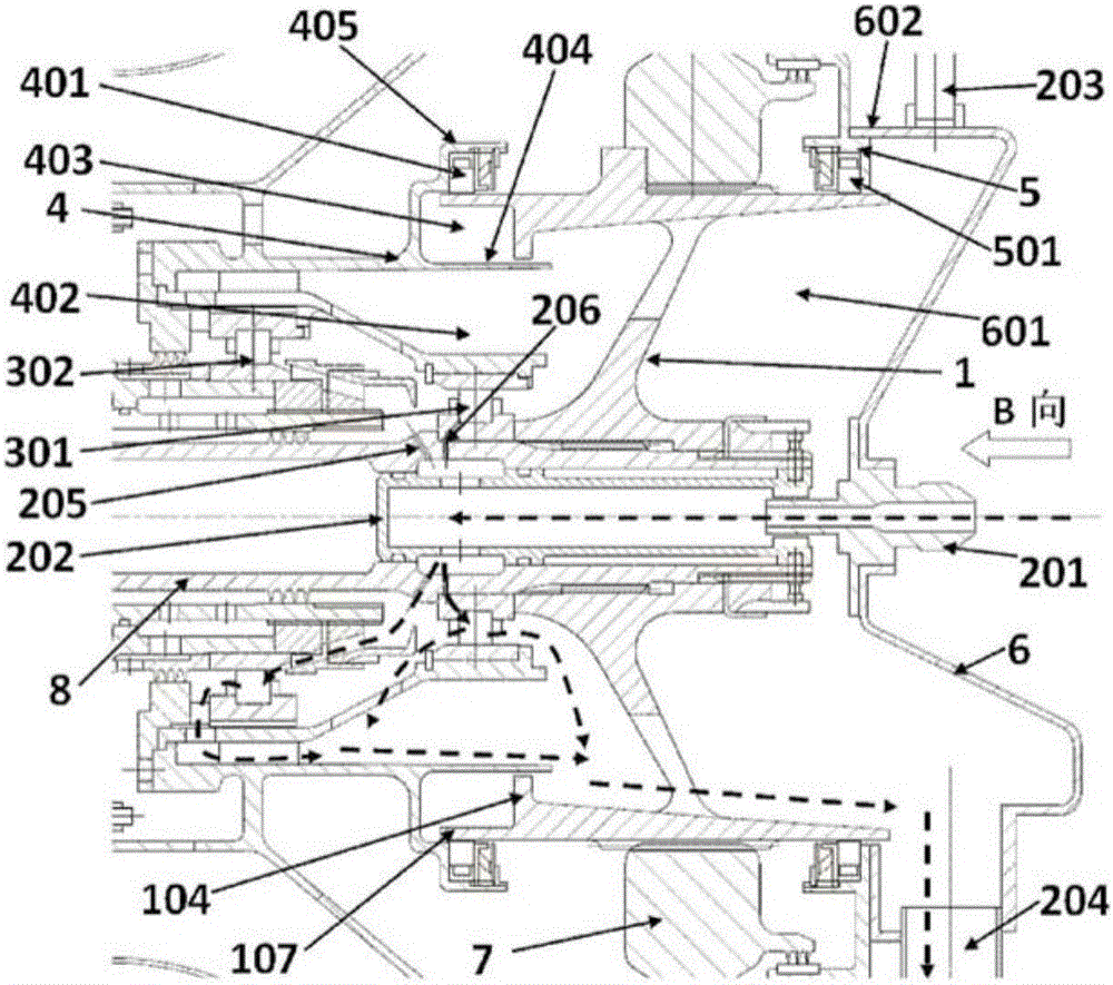
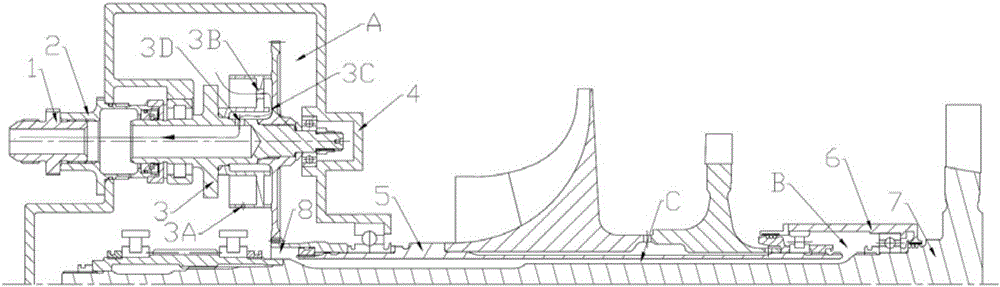
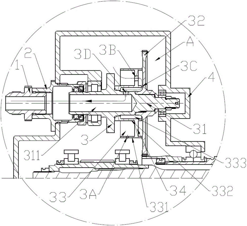
[0022] Such as figure 2 , 3 As shown, the axial ventilation structure of the engine bearing cavity of the present invention is especially suitable for gas turbine engines, including the engine cold end component bearing cavity A and the engine hot end component bearing cavity B, and the engine cold end component includes engine fan, compressor and / or Or reduction drive gear components, engine hot end components including engine combustion chamber and / or turbine components. The bearing chamber A of the cold end part of the engine is composed of the rotor part of the cold e...


PUM


Abstract

The invention relates to an axle center ventilating structure and a gas turbine engine. A bearing chamber of a cold end component of the engine communicates with a bearing chamber of a hot end component of the engine, a ventilating system is used for maintaining the pressure of the bearing chamber of the cold end component of the engine to be the same with that of the bearing chamber of the hot end component of the engine basically, the bearing chamber of the cold end component communicates with an engine nozzle through a centrifugal oil-gas separator, an oil-gas mixture in the bearing chamber of the hot end component enters the bearing chamber of the cold end component of the engine via an axle center ventilating cavity, then the oil-gas mixture in the bearing chamber of the hot end component and an oil-gas mixture of the bearing chamber of the cold end component are subjected to oil-gas separation together by the centrifugal oil-gas separator, and the unseparated oil-gas mixture is discharged via the engine nozzle. The bearing chamber axle center ventilating structure of the engine is simple and is convenient to design and adjust, the bearing chamber of the cold end component communicates with the bearing chamber of the hot end component, the pressure of the bearing chamber of the cold end component and the pressure of the bearing chamber of the hot end component can be ensured to be almost the same, design and adjustment of a secondary air system are facilitated, faults of the engine due to leakage of lubricating oil and unsmooth circulation are reduced, the reliability of the engine is improved, meanwhile, heat transmission from the bearing chamber of the hot end component to the bearing chamber of the cold end component can be improved, and therefore, the quantity of lubricating oil required for cooling a bearing of the hot end component is reduced.

Description

technical field [0001] The invention relates to a shaft-centered ventilation structure of a bearing cavity and a gas turbine engine with the structure, in particular to a gas turbine engine that is applied to a bearing cavity of a cold-end part and a bearing cavity of a hot-end part and maintains the pressure of the two chambers basically the same An axial ventilation structure and a gas turbine engine with the structure. Background technique [0002] The gas turbine engine lubricating oil system is an important part of the aviation gas turbine engine. Its main function is to lubricate and cool the rotor fulcrum bearings, transmission gears and other components of the engine. Separation is carried out, the lubricating oil is left in the bearing cavity to continue to participate in the circulation, and the unseparated oil-air mixture is discharged from the engine to maintain pressure balance. [0003] In each bearing chamber of a gas turbine engine, there is usually a lubric...

Claims


Application Information

Patent Timeline
Patent Type & Authority Applications(China)
IPC IPC(8): F02C7/06
CPCF02C7/06
Inventor 阳诚武赵胜丰卢新根韩戈朱俊强
Owner INST OF ENGINEERING THERMOPHYSICS - CHINESE ACAD OF SCI
Why Eureka
Try Eureka