Motor control device

A control device and motor technology, which is applied in the direction of multiple motor speed adjustment, etc., can solve the problems that it is difficult to fully improve the control responsiveness of the servo controller, it is difficult to improve the synchronization accuracy between axes, and it is difficult to fully suppress the errors of modules and servo controllers.

Active Publication Date: 2016-08-24
SANYO DENKI CO LTD
View PDF6 Cites 3 Cited by
  • Summary
  • Abstract
  • Description
  • Claims
  • Application Information

AI Technical Summary

Problems solved by technology

As a result, it is difficult to sufficiently improve the control responsiveness of the servo controller related to each axis
When the control responsiveness of the servo controller related to each axis is not high, it is difficult to sufficiently suppress the error between the module and the servo controller (control of the servo controller)
When it is difficult to sufficiently suppress the error between the control of the module and the servo controller, it is difficult to improve the synchronization accuracy between the axes

Method used


Image

  • Motor control device
  • Motor control device
  • Motor control device

Examples


no. 1 approach

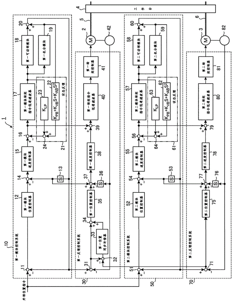
[0121] figure 1 It is a block diagram of the motor control device 1 according to the first embodiment of the present invention. figure 1 The shown motor control device 1 uses two motors, a first motor 2 and a second motor 3, to jointly drive one movable part. Thereby, the motor control device 1 can specify the position of the movable part at high speed and with high precision.

[0122] like figure 1 As shown, the motor control device 1 has: a first module control system 10 , a first feedback control system 30 , a second module control system 50 and a second feedback control system 70 .

[0123] An external position command indicating the control position of the table 4 as a movable part is input to the first module control system 10 . The first module control system 10 generates various first module instructions.

[0124] The first feedback control system 30 has a feedback loop including the first electric motor 2 . The first feedback control system 30 actually controls t...

no. 2 approach

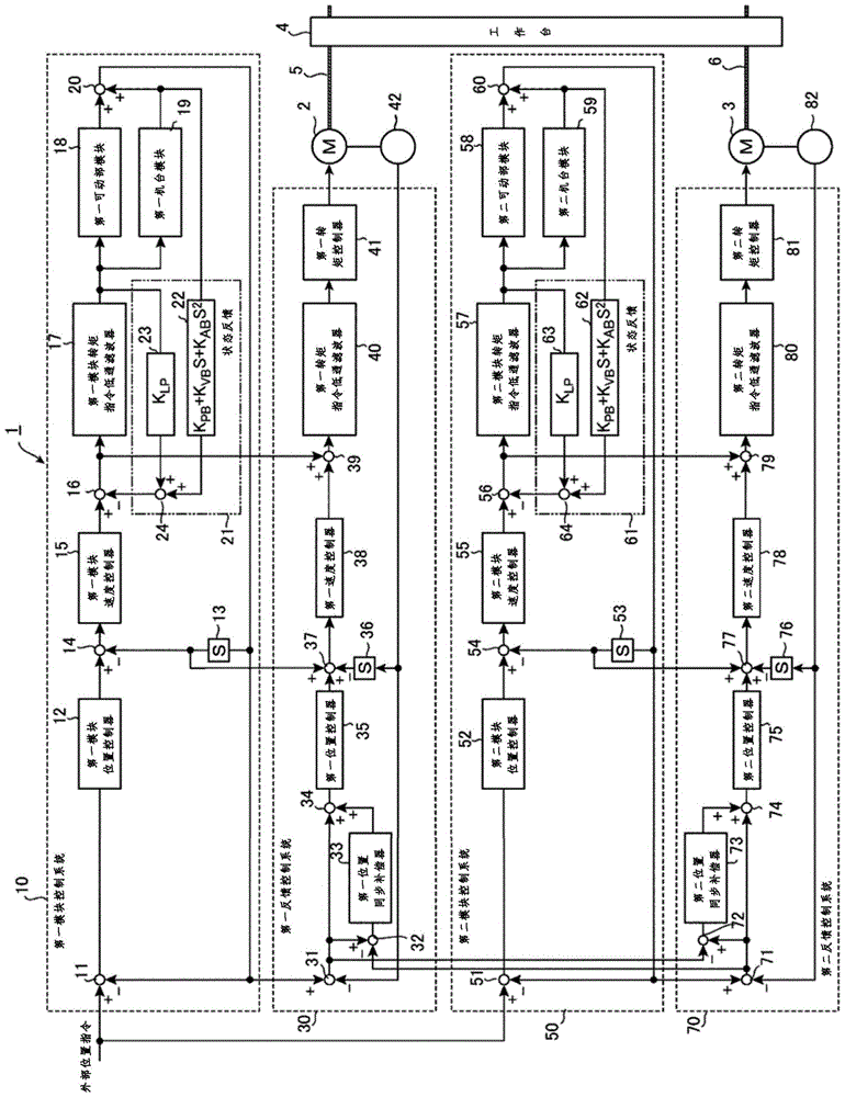
[0199] figure 2 It is a block diagram of a motor control device 1 according to a second embodiment of the present invention. figure 2 The motor control device 1 shown with figure 1 The difference between the devices shown is that the second feedback control system 70 has a second synchronous position error obtainer 72 , a second position synchronous compensator 73 and a second synchronous compensation position error obtainer 74 .

[0200] The second synchronous position error obtainer 72, the second position synchronous compensator 73 and the second synchronous compensation position error obtainer 74 correspond to the first synchronous position error obtainer 32, the first position synchronous compensator 33 and the first synchronous compensation position Error acquirer 34.

[0201] Based on the second control position error acquired by the second control position error acquirer 71 and the first control position error acquired by the first control position error acquirer 3...

no. 3 approach

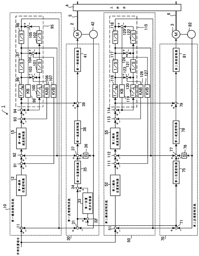
[0210] image 3 It is a block diagram of a motor control device 1 according to a third embodiment of the present invention. image 3 The motor control device 1 shown has: a first modular control system 10 , a first feedback control system 30 , a second modular control system 50 and a second feedback control system 70 . image 3 The motor control device 1 shown with figure 1 Similarly, the motor control device 1 shown uses two motors, the first motor 2 and the second motor 3, to jointly drive one movable part. Thereby, the motor control device 1 can determine the position of the movable part at high speed and with high precision.

[0211] Below, around the figure 1 Differences from the illustrated motor control device 1 will be described. Additionally, with figure 1 The same structural elements of the shown motor control device 1 are adopted as figure 1 The same reference numerals are used, and descriptions thereof are omitted.

[0212] The first feedback control system ...


PUM


Abstract

The invention provides a motor control device that drives a movable portion by N (N: a natural number more than 2) motors driven by a common external command, the motor control device comprising: a module control system that feeds back a state to suppress an influence on the vibration of the movable portion and generates a module instruction including a module position instruction based on the external command; and N feedback control systems arranged to be one-to-one correspondent to the motors and carrying out feedback control on the motors one the basis of the module instruction. (N-1) feedback control systems compensate control errors in controlling each of the motors by utilizing a difference between a respective control error and a control error in the remaining one of the feedback control systems so as to realize high-speed and high-precision positioning.

Description

technical field [0001] The invention relates to a motor control device. Background technique [0002] In component mounting machines such as chip mounters, the number of components mounted per unit time can be increased by driving the movable portion with a motor at high speed to perform high-precision positioning. Thereby, the manufacturing cost related to component mounting work can be reduced. For example, in a large-scale chip mounter that uses a large movable part that can simultaneously mount a plurality of printed circuit boards, it is conceivable to drive one movable part at high speed by a plurality of motors. [0003] For example, in the motor control device described in Japanese Patent Laid-Open Publication No. 2003-345442, one movable part is driven by two motors. The two motors are respectively controlled by corresponding motor control modules and servo controllers. The servo controller actually controls the motion of the motor based on external position comm...

Claims


Application Information

Patent Timeline
Patent Type & Authority Applications(China)
IPC IPC(8): H02P5/52
Inventor 井出勇治北原通生平出敏雄
Owner SANYO DENKI CO LTD
Why Eureka
Try Eureka