Uterus haemostatic forceps

A technology of hemostatic forceps and implanting uterus, which is applied in the field of uterine hemostatic forceps to achieve the effect of novel structure, easy operation and avoiding massive bleeding

Inactive Publication Date: 2016-10-26
JIANGSU PROVINCE HOSPITAL
View PDF10 Cites 3 Cited by
  • Summary
  • Abstract
  • Description
  • Claims
  • Application Information

AI Technical Summary

Problems solved by technology

However, the hemostatic forceps currently on the market are mostly used for clamping hemostasis of local blood vessels (elbow, straight head hemostatic forceps), and at most are clamping hemostasis of local tissues (such as oval forceps), lacking a kind of forceps that can clamp the whole uterine organs hemostatic tool

Method used


Image

  • Uterus haemostatic forceps
  • Uterus haemostatic forceps
  • Uterus haemostatic forceps

Examples


Embodiment 1

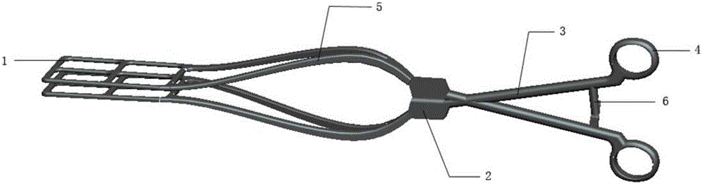
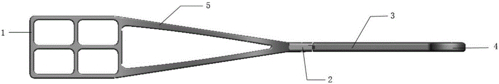
[0024] Such as figure 1 with 2 As shown, the uterine body and lower segment hemostatic forceps include: two rectangular forceps heads 1 , two curved forceps handles, a rotating shaft 2 , two forceps arms 3 and two handles 4 . Wherein the crank handle comprises two crank handles 5 .

[0025] Wherein the rectangular pliers head is a hollow rectangle with rounded edges, the length of the rectangle is 5-8 cm, and the width is 4-5 cm. The front ends of the crank handles are separated from each other and connected to the rectangular pliers heads, and the tails are connected to the pliers arms. The two crank handles and the pliers arms form a Y shape, and a handle is provided at the tail end of the pliers arms; the rotating shaft is set on the curved pliers handle and the pliers arms. In the middle, the two curved pliers handles and the pliers arms are cross-connected and can be fastened or opened along the rotating shaft. After the fastening, the two rectangular pliers heads are t...

Embodiment 2

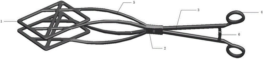
[0029] Such as image 3 with 4 As shown, the lower uterine segment hemostatic forceps includes: two rectangular forceps heads 1 , two curved forceps handles, a rotating shaft 2 , two forceps arms 3 and two handles 4 . Wherein the crank handle comprises two crank handles 5 .

[0030] Wherein the rectangular pliers head is a hollow rectangle with rounded edges, the length of the rectangle is 5-8 cm, and the width is 4-5 cm. The front ends of the crank handles are separated from each other and connected to the rectangular pliers heads, and the tails are connected to the pliers arms. The two crank handles and the pliers arms form a Y shape, and a handle is provided at the tail end of the pliers arms; the rotating shaft is set on the curved pliers handle and the pliers arms. In the middle, the two curved pliers handles and the pliers arms are cross-connected and can be fastened or opened along the rotating shaft. After the fastening, the two rectangular pliers heads are tightly f...


PUM


Abstract

The invention discloses a pair of uterus haemostatic forceps. The uterus haemostatic forceps include two rectangular forceps heads, two curve forceps rods, a rotation shaft, two forceps arms and two handles; the rectangular forceps heads are of hollow rectangular structures and are arranged at the front end of the curve forceps rods; the curve forceps rods are convex curve-shaped, and the tails of the curve forceps rods are connected to the forceps arms; the tail ends of the forceps arms are provided with the handles; the rotation shaft is arranged between the curve forceps rods and the forceps arms, can allow the two curve forceps rods and the forceps arms to be connected in a cross manner and open and close along the rotation shaft, wherein after closure, the two rectangular forceps heads are attached to each other tightly, and a hollow structure is form between the two curve forceps rods. The uterus haemostatic forceps are novel in structure, is easy to operate, can be used for clamping Caesarean delivery (after delivery of baby) corpus uteri, in particular to the front and back walls of the lower section of the uterus, can achieve a compression hemostasis effect on the whole organ so as to prevent short-term excessive bleeding of placenta attachment sites, can match uterine artery embolisation, hysterectomy and call aid treatment, and ensure life safety of puerperae.

Description

technical field [0001] The invention belongs to the technical field of medical surgical instruments, in particular to a uterine hemostatic forceps capable of clamping the uterus for obstetrics and gynecology operations. Background technique [0002] At present, when obstetricians and gynecologists perform operations on puerpera, hemostatic forceps are commonly used and most used. However, the hemostatic forceps currently on the market are mostly used for clamping hemostasis of local blood vessels (elbow, straight head hemostatic forceps), and at most are clamping hemostasis of local tissues (such as oval forceps), lacking a kind of forceps that can clamp the whole uterine organs Hemostasis tool. [0003] Chinese patent CN201410086066.7 discloses a hemostatic forceps for obstetrics and gynecology. The upper forceps head and the lower forceps head are provided with protrusions and depressions that engage with each other, and the rack design is adopted, which can be effectivel...

Claims


Application Information

Patent Timeline
Patent Type & Authority Applications(China)
IPC IPC(8): A61B17/12A61B17/42A61B17/28
CPCA61B17/12A61B17/2812A61B17/282A61B17/42A61B2017/12004A61B2017/4216
Inventor 韩平
Owner JIANGSU PROVINCE HOSPITAL
Why Eureka
Try Eureka