Sliding component

一种滑动部件、滑动面的技术,应用在发动机元件、发动机的密封、机械设备等方向,能够解决泄漏量增多、缺少顺畅性、流体推回等问题,达到削减泄漏量、提高配置效率、压力梯度减小的效果

Active Publication Date: 2016-11-09
EAGLE INDS
View PDF9 Cites 9 Cited by
  • Summary
  • Abstract
  • Description
  • Claims
  • Application Information

AI Technical Summary

Problems solved by technology

[0005] However, in the invention described in the above-mentioned Patent Document 1, when there is a pressure difference between the inner and outer peripheries of the sliding surface of the seal, etc., it is necessary to overcome the suction action of the pressure, and the fluid cannot be pushed back due to the magnitude of the pressure. in the case of
Therefore, when the pressure difference is small, leakage can be prevented, but there is a problem that the leakage amount increases when the pressure difference is large.
[0006] In addition, the above-mentioned prior art 2 is an epoch-making invention in that it has two functions of leakage prevention and lubrication regardless of the magnitude of the pressure difference between the inner and outer peripheries of the sliding surface, but there is the following problem: the basic shape of each dimple 50 is crank shape, thus slightly lacking smoothness in the movement of the fluid from the cavitation forming region 50a on the upstream side to the positive pressure generating region 50b on the downstream side, so the dynamic pressure generation at the low-pressure fluid side X of the positive pressure generating region 50b changes. If it is too large, it may cause leakage, and in addition, the distance from the pressure peak position of the dynamic pressure generating area to the low-pressure fluid side is not so large, so it may cause leakage

Method used


Image

  • Sliding component
  • Sliding component
  • Sliding component

Examples


Embodiment 1

[0037] refer to Figure 1 to Figure 3 , the sliding member of Embodiment 1 of the present invention will be described.

[0038] In addition, in this embodiment, a case where the member constituting the mechanical seal is a sliding member will be described as an example.

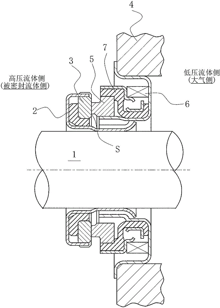
[0039] figure 1 It is a vertical cross-sectional view showing an example of a mechanical seal, and is an inner type mechanical seal that seals the sealed fluid on the high-pressure fluid side that leaks from the outer circumference of the sliding surface toward the inner circumference, and is annular. The rotary ring 3 and the annular fixed ring 5 are pressed between the sliding surfaces S which are mirror-finished by grinding etc. The rotating ring 3 is provided on the side of the rotating shaft 1 that drives the pump impeller (not shown) on the side of the high-pressure fluid in a state capable of rotating integrally with the rotating shaft 1 via the sleeve 2. The fixed ring 5 It is provided in the casi...

Embodiment 2

[0061] Figure 4 It is a figure showing the sliding surface of the sliding member of Example 2 of the present invention, in order to figure 1 The case where a dent is formed on the sliding surface of the fixing ring 5 will be described as an example. Embodiment 2 is the same as figure 2 The shown embodiment 1 is different: a positive pressure generating mechanism composed of Rayleigh steps is arranged on the high-pressure fluid side of the sliding surface provided with dimples, but other aspects are basically the same as embodiment 1, and the same parts are marked the same , and omit repeated descriptions.

[0062] exist Figure 4 Among them, on the sliding surface S, dimples 10 are arranged on the low-pressure fluid side, and a positive pressure generating mechanism composed of Rayleigh steps 20 is arranged on the high-pressure fluid side.

[0063] The Rayleigh step 20 is composed of a narrowed step 21, a groove portion 22, and a radial groove 23 communicating with the ...

Embodiment 3

[0068] Figure 5 It is a figure showing the sliding surface of the sliding member of Example 3 of the present invention, in order to figure 1 The case where a dent is formed on the sliding surface of the fixing ring 5 will be described as an example. Embodiment 3 is the same as figure 2 The shown embodiment 1 is different: a positive pressure generating mechanism composed of Rayleigh steps is arranged on the high-pressure fluid side of the sliding surface provided with dimples, but other aspects are basically the same as embodiment 1, and the same parts are marked the same , and omit repeated descriptions.

[0069] exist Figure 5 Among them, on the sliding surface S, dimples 10 are arranged on the low-pressure fluid side, and a positive pressure generating mechanism composed of Rayleigh steps 30 is arranged on the high-pressure fluid side.

[0070] The Rayleigh step 30 is composed of a narrowed step 31, a groove portion 32, and a radial direction groove 33 communicating...


PUM


Abstract

Movement of a fluid from a cavitation region, which is on the upstream side of a dimple formed in a sliding surface, to a positive pressure generation region on the downstream side is smoothened. The present invention is characterized in that: a plurality of dimples (10) are provided independently in the circumferential direction of one sliding surface of a pair of sliding components that slide relative to each other; a cavitation formation region (10a) on the upstream side of the dimples (10) is disposed toward a low-pressure fluid side, a positive pressure generation region (10b) on the downstream side is disposed toward a high-pressure fluid side; and the low-pressure fluid-side edge (10d) of the positive pressure generation region (10b) forms a tapered shape inclined along the rotational direction of an opposing sliding surface from the low-pressure fluid side toward the high-pressure fluid side, and is smoothly connected to the low-pressure fluid-side end of the cavitation formation region (10a).

Description

technical field [0001] The present invention relates to sliding parts suitable for use in, for example, mechanical seals, bearings, and other sliding parts. In particular, it relates to sliding parts such as seal rings and bearings that require fluid to intervene on sliding surfaces to reduce friction and prevent fluid leakage from the sliding surfaces. Background technique [0002] In a mechanical seal as an example of a sliding member, in order to maintain the sealing performance for a long period of time, it is necessary to balance the contradictory conditions of "sealing" and "lubrication". In particular, in recent years, due to environmental protection and the like, in order to prevent leakage of the sealed fluid and reduce mechanical loss, the demand for lower friction has been further increased. As a method of reducing friction, it is possible to achieve a so-called fluid lubrication state in which dynamic pressure is generated between sliding surfaces by rotation an...

Claims


Application Information

Patent Timeline
Patent Type & Authority Applications(China)
IPC IPC(8): F16J15/34
CPCF16J15/3412F16J15/34F16J15/40
Inventor 板谷壮敏德永雄一郎
Owner EAGLE INDS
Why Eureka
Try Eureka