A multifunctional power cabinet

A power cabinet and multi-functional technology, applied in the direction of electrical components, pull-out switch cabinets, anti-theft alarm mechanical start, etc., can solve the problems of shell material loss, real-time movement, unsatisfactory strength and corrosion resistance, etc., to achieve Prevents the effect of vandalism or theft

Active Publication Date: 2018-05-18
南京佳盛机电器材制造有限公司
View PDF7 Cites 0 Cited by
  • Summary
  • Abstract
  • Description
  • Claims
  • Application Information

AI Technical Summary

Problems solved by technology

[0002] The power cabinet is a very critical equipment in the power supply equipment. The current power cabinet can only solve its routine tasks and pay little attention to the performance of the cabinet itself. For example, because it may work outdoors for a long time, its safety is difficult to be guaranteed. In order to prevent the existing power cabinet from being damaged, it is conventionally fixed on the ground. However, since the power cabinet often needs to be moved in real time, if it is fixed on the ground, it will not be able to move in real time and a new control cabinet unit needs to be added. greatly increase the cost
And because it is very important to resist the damage of external weather to internal components when it works outdoors, the existing control cabinets are usually made of ordinary carbon steel with paint and anti-rust materials, and the strength and corrosion resistance are not very ideal. , since the internal components are all expensive power components, not paying attention to the research and development of the shell material may cause very large losses

Method used


Image

  • A multifunctional power cabinet
  • A multifunctional power cabinet
  • A multifunctional power cabinet

Examples


Embodiment 1

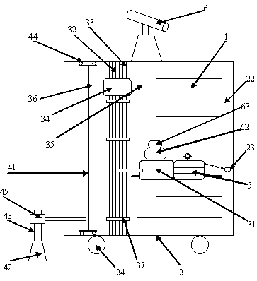
[0034] The utility model relates to a multifunctional electric cabinet, comprising: a drawer part, a drawer push-pull device, a position control device, an alarm device, a monitoring device and a casing.

[0035] The drawer part includes a plurality of power control drawer boxes and power control parts arranged in the plurality of power control drawer boxes, and the front end of the drawer part is provided with a button for controlling the power control drawer box to go in and out.

[0036] The drawer push-pull device includes a lifting drive motor arranged inside the casing, a vertically arranged spiral lifting rod connected with the lifting drive motor, a position positioning rod arranged adjacent to the spiral lifting rod, and a push-pull drive arranged on the spiral lifting rod. The motor and the push-pull rods arranged on the left and right sides of the push-pull drive motor.

[0037] The push-pull rod includes a first push-pull rod detachably connected with the electric ...

Embodiment 2

[0054] The utility model relates to a multifunctional electric cabinet, comprising: a drawer part, a drawer push-pull device, a position control device, an alarm device, a monitoring device and a casing.

[0055] The drawer part includes a plurality of power control drawer boxes and power control parts arranged in the plurality of power control drawer boxes, and the front end of the drawer part is provided with a button for controlling the power control drawer box to go in and out.

[0056] The drawer push-pull device includes a lifting drive motor arranged inside the casing, a vertically arranged spiral lifting rod connected with the lifting drive motor, a position positioning rod arranged adjacent to the spiral lifting rod, and a push-pull drive arranged on the spiral lifting rod. The motor and the push-pull rods arranged on the left and right sides of the push-pull drive motor.

[0057] The push-pull rod includes a first push-pull rod detachably connected with the electric ...


PUM


Abstract

The invention relates to a multifunctional electric power cabinet. The multifunctional electric power cabinet comprises a drawer component, a drawer push-and-pull device, a position control device, a warning device, a monitoring device and a shell. By improving the components and improving the connection manner and coordination manner among the components, the multifunctional electric power cabinet is portable and detachable, and the effects of burglary prevention, rust prevention and the like are realized.

Description

technical field [0001] The invention belongs to the field of electric equipment, and in particular relates to a multifunctional electric cabinet. Background technique [0002] The power cabinet is a very critical equipment in the power supply equipment. The current power cabinet can only solve its routine tasks, and pays little attention to the performance of the cabinet itself. For example, because it may work outdoors for a long time, its safety is difficult to be guaranteed. In order to prevent the existing power cabinet from being damaged, it is conventionally fixed on the ground. However, since the power cabinet often needs to be moved in real time, if it is fixed on the ground, it will not be able to move in real time and a new control cabinet unit needs to be added. Greatly increase the cost. And because it is very important to resist the damage of external weather to internal components when it works outdoors, the existing control cabinets are usually made of ordina...

Claims


Application Information

Patent Timeline
Patent Type & Authority Patents(China)
IPC IPC(8): H02B11/127G08B13/06
CPCG08B13/06H02B11/127
Inventor 倪恩来孙修胜
Owner 南京佳盛机电器材制造有限公司
Why Eureka
Try Eureka