Flow splitter for low pressure compressor of axial turbomachine with de-icing annular duct

An axial-flow turbine and compressor technology, applied in the field of low-pressure compressors, can solve problems such as catheter rupture, and achieve the effects of promoting expansion, reducing the risk of fracture, and reducing mechanical restrictions

Active Publication Date: 2017-01-25
SAFRAN AERO BOOSTERS SA
View PDF7 Cites 3 Cited by
  • Summary
  • Abstract
  • Description
  • Claims
  • Application Information

AI Technical Summary

Problems solved by technology

However, the rigid connection of the annular duct with respect to the casing creates a risk involving rupture of the conduit

Method used


Image

  • Flow splitter for low pressure compressor of axial turbomachine with de-icing annular duct
  • Flow splitter for low pressure compressor of axial turbomachine with de-icing annular duct
  • Flow splitter for low pressure compressor of axial turbomachine with de-icing annular duct

Examples


Embodiment Construction

[0041] In the following description, the terms "inner" or "inner" and "outer" or "external" refer to a position relative to the axis of rotation of the axial turbine. The axial direction corresponds to a direction along the axis of rotation of the turbine. The radial direction is perpendicular to the axis of rotation.

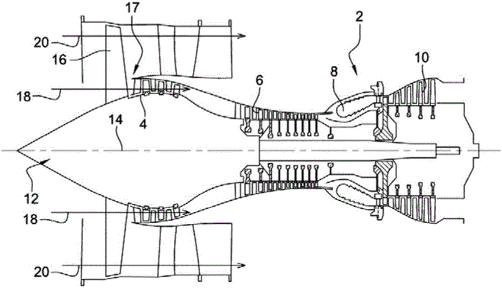
[0042] figure 1is a simplified illustration of an axial turbine 2 for an aircraft. In this case it is a twin-flow turbocharger. The turbocharger 2 includes a first compression stage called a low-pressure compressor 4 , a second compression stage called a high-pressure compressor 6 , a combustion chamber 8 and one or more turbine stages 10 . During operation, the mechanical power of the turbine 10 is transmitted via a central shaft to the rotor 12 which moves the two compressors 4 and 6 . These compressors include rows of rotor blades associated with associated rows of stator blades. The rotation of the rotor about its axis of rotation 14 thus allows an ai...


PUM


Abstract

The invention consists of a separation nozzle (17) for an axial turbomachine, in particular a compressor (4), said spout comprising: an annular casing (30); an annular conduit (34) for defrosting a separation edge ) Of the spout; The duct (34) is connected to the envelope (30) only at a first zone (42) at a hot air inlet (36) and at a second zone (64) located at a position diametrically opposite to Said inlet or an angle (positive and negative) of less than 30 degrees with said position, with respect to the axis (14) of the turbomachine, so as to allow expansion deformation of the duct. The invention also consists of a compressor (4) and a turbomachine comprising such a spout (17).

Description

technical field [0001] The invention relates to the field of axial turbomachines. More specifically, the present invention relates to a split tip for a low pressure compressor of an axial turbine comprising an annular deicing duct. The invention also relates to a low pressure compressor. Background technique [0002] The split tip of the low pressure compressor of an aircraft turbine comprises a split edge which is subjected to ice accumulation during flight. This ice accumulation originates from flight conditions, especially from high-altitude temperatures. Ice that breaks away from the separation edge can be sucked into the compressor and damage the turbine, and accumulated ice can also reduce the output of the turbine. In order to overcome this phenomenon, it is known to provide a split head with de-icing means by circulating hot air in the circulating head. [0003] Published patent document EP0918150A1 discloses a split tip of a turbomachine comprising an annular ca...

Claims


Application Information

Patent Timeline
Patent Type & Authority Applications(China)
IPC IPC(8): F02C7/047
CPCB64D2033/0233F02C7/047F01D25/02F04D29/584F05D2260/30B64D15/04B64D33/02F01D25/10F04D29/522F04D29/542F04D29/545F05D2220/323F05D2250/141
Inventor J-F.科特奎斯
Owner SAFRAN AERO BOOSTERS SA
Why Eureka
Try Eureka