
Vibratory branch accumulated snow removing device
A technology of equipment and branches, applied in the field of snow removers, can solve the problems of low efficiency, affect snow removal effect, high labor intensity, etc., and achieve the effect of improving snow removal efficiency, significant snow removal effect, and reducing labor intensity.
- Summary
- Abstract
- Description
- Claims
- Application Information
AI Technical Summary
Problems solved by technology
Method used
Image

Examples
Embodiment
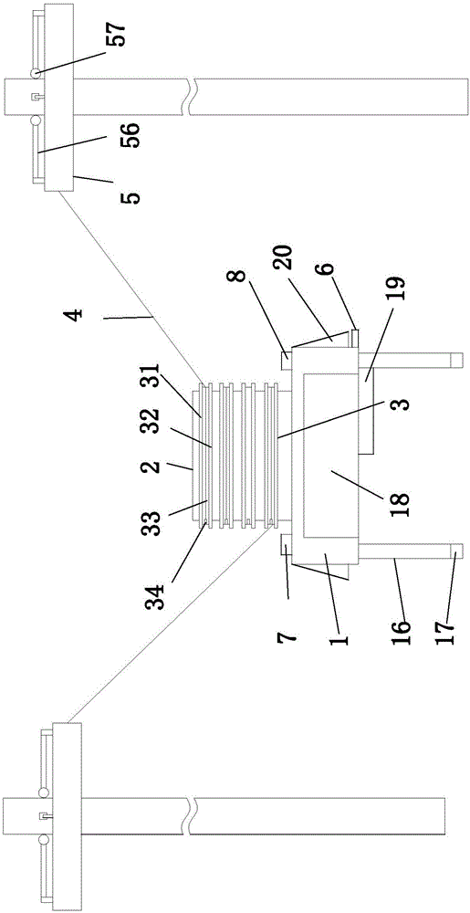
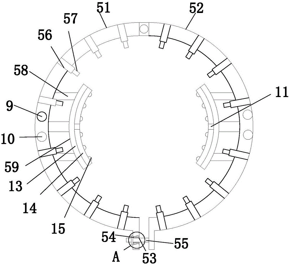
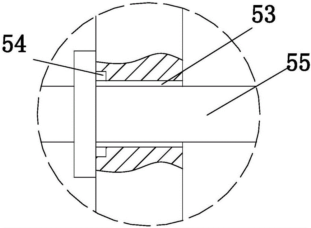
[0022] Embodiment: a kind of vibration removal equipment for branches and snow, constitutes as Figure 1 to Figure 6 As shown, including a base 1, a vibrating motor 2 is arranged above the base 1, and a multi-layer winding device 3 is arranged outside the vibrating motor 2, and a connecting rope 4 is arranged on the winding device 3, and a crawler Tree device 5; described tree climbing device 5 comprises a first semicircular ring 51 and a second semicircular ring 52, and one end of the first semicircular ring 51 is provided with a fixing hole 53, and the fixing hole 53 is provided with an inductor 54, and the second semicircular ring 51 is provided with a fixing hole 53; One end of the semicircular ring 52 is provided with a stud 55; the other end of the second semicircular ring 52 and the first semicircular ring 51 is connected through a rotating pair; the upper end of the first semicircular ring 51 and the second semicircular ring 52 A symmetrically arranged hydraulic telesc...
PUM
 Abstract
Description
Claims
Application Information