Image stitching method and image stitching device

A stitching device and image technology, which is applied in the field of image processing, can solve the problems of small size difference, low image accuracy, and inconspicuous extracted image feature information, and achieve the effect of high-precision image stitching and enlarged field of view

Active Publication Date: 2019-09-03
IND TECH RES INST
View PDF3 Cites 0 Cited by
  • Summary
  • Abstract
  • Description
  • Claims
  • Application Information

AI Technical Summary

Problems solved by technology

However, in the raw material inspection, that is to spread the sauces and fillings in the ingredients in a detection area, and pick out the problematic impurities and debris, and these sauces and fillings have little difference in size between each other, so in The feature information of the extracted image is relatively inconspicuous, which not only reduces the accuracy of the resulting image after the subsequent image superposition, but also makes detection difficult

Method used


Image

  • Image stitching method and image stitching device
  • Image stitching method and image stitching device
  • Image stitching method and image stitching device

Examples


Embodiment Construction

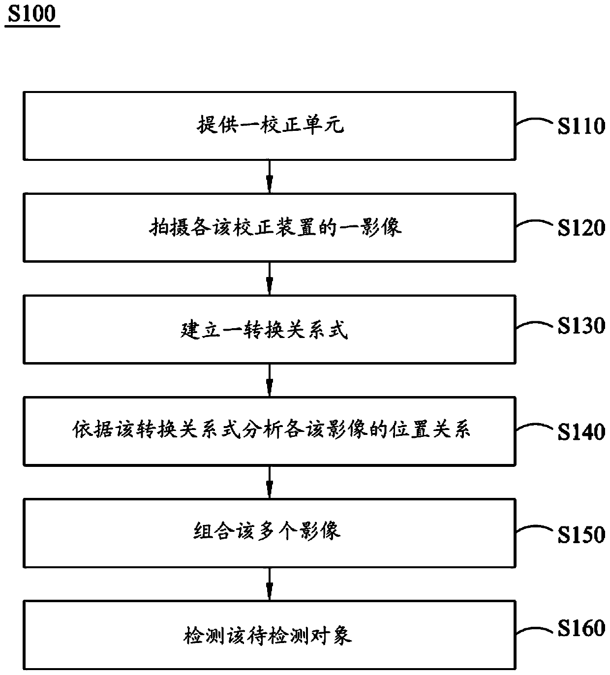
[0060] The specific implementation manner of the present invention will be further described below in conjunction with the accompanying drawings and embodiments. The following examples are only used to illustrate the technical solutions of the present invention more clearly, but not to limit the protection scope of the present invention.

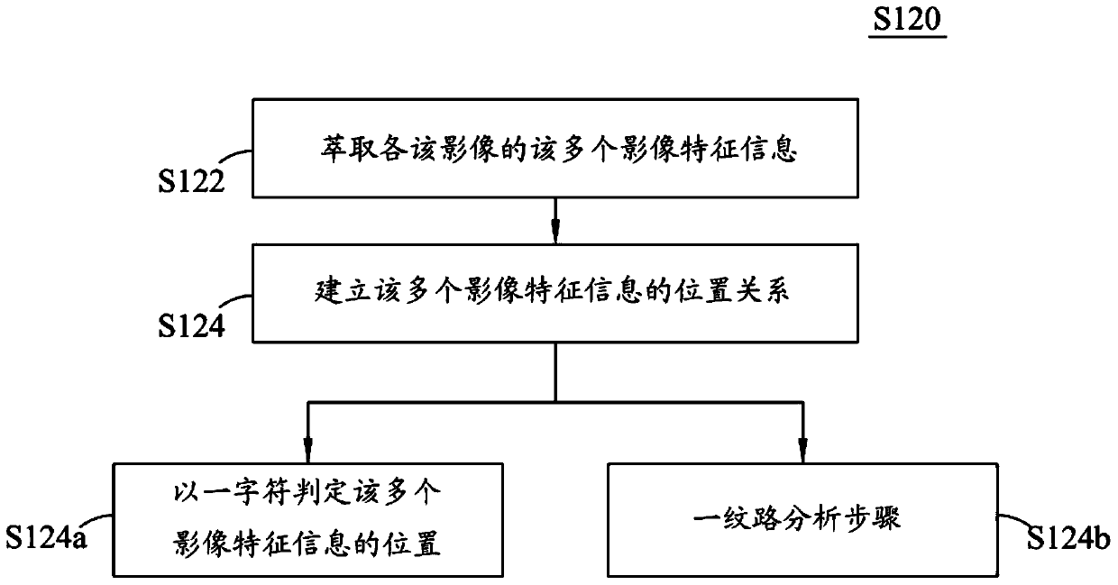
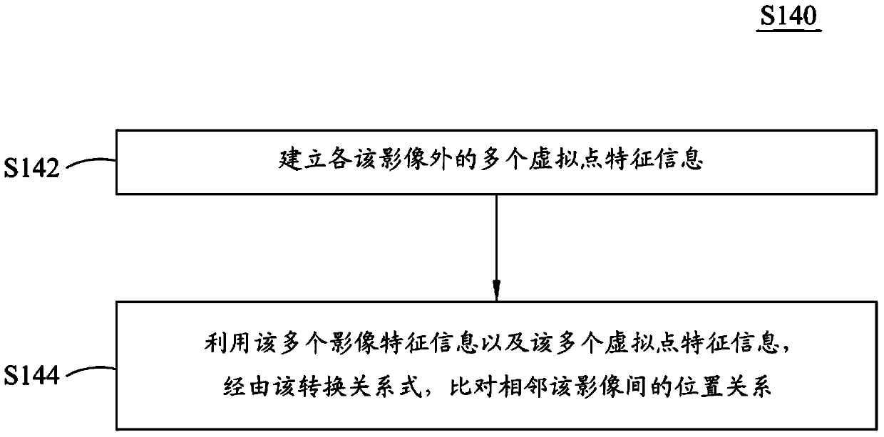
[0061] figure 1 It is a flow chart of the image stitching method of the present invention. Please refer to figure 1 . The image stitching method S100 includes the following steps S110-S160.

[0062] In the image stitching method S100, a calibration unit 110 is firstly provided in step S110.

[0063] Such as Figure 4 as shown, Figure 4 It is a schematic diagram of the image stitching device of the present invention. The image stitching device 100 includes a correction unit 110, a plurality of image capturing units (image capturing unit) 120 and a processing unit (process unit) 130, wherein the processing unit 130 is coupled to the im...


PUM


Abstract

The invention discloses an image stitching method and an image stitching device. The image stitching method includes the following steps. A calibration unit is provided, wherein a calibration device of the calibration unit contains a plurality of known characteristic information. Take an image of the calibration device. Create conversion relations. The positional relationship of the image is analyzed according to the transformation relation. Combine multiple images.

Description

technical field [0001] The present invention relates to an image processing technology, and in particular to an image stitching method and an image stitching device using multi-shot technology without overlapping images. Background technique [0002] In recent years, machine vision detection methods have been widely used in industrial automation. With the improvement of processing capacity, the requirements for detection accuracy are getting higher and higher. In the same range of detection of the viewing area, generally speaking, the method to improve the accuracy is to replace the camera with higher pixels or increase the number of shooting devices, or to reduce the viewing area, sacrifice the visible range, and use a higher magnification lens for higher resolution. In this way, although the accuracy may be improved, the workpiece to be detected or the detection range cannot be completely included in the field of view of the lens, resulting in the inability to perform det...

Claims


Application Information

Patent Timeline
Patent Type & Authority Patents(China)
IPC IPC(8): H04N5/262
CPCG06T2207/30204G06T7/337G06T3/4038H04N23/698G06K15/027G06T2207/20212G06T7/40G06T2207/10141G06T2207/20221
Inventor 张津魁吕尚杰邱威尧江博通
Owner IND TECH RES INST
Why Eureka
Try Eureka