Bridge monitoring equipment

A technology for monitoring equipment and bridges, applied in the field of monitoring equipment, can solve the problems of easy short-circuit failure, cumbersome disassembly and assembly process, time-consuming and labor-intensive efficiency, etc., so as to improve the efficiency of installation and maintenance, reduce installation steps, and improve work efficiency. Effect

Inactive Publication Date: 2017-05-31
何燕锋
View PDF0 Cites 1 Cited by
  • Summary
  • Abstract
  • Description
  • Claims
  • Application Information

AI Technical Summary

Problems solved by technology

When the existing monitoring probes are installed, the probes are generally fixed on the poles by screws, and then powered by external lines. It is cumbersome, time-consuming, labor-intensive and inefficient. At the same time, because the external circuit of the probe is exposed to the outside world, short-circuit faults are prone to occur during long-term use, which affects normal work and easily induces electric shock accidents. security risks

Method used


Image

  • Bridge monitoring equipment
  • Bridge monitoring equipment
  • Bridge monitoring equipment

Examples


Embodiment Construction

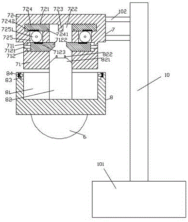
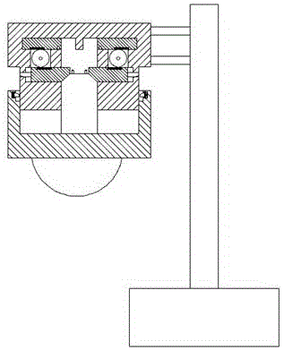
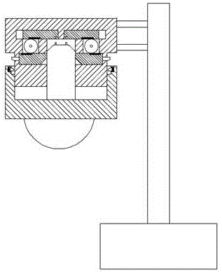
[0020] Such as Figure 1-Figure 5 As shown, a bridge monitoring device of the present invention includes a fixed base 7 composed of an upper base body 72 and a lower base body 71 and an assembly 8 with a monitoring probe 6 arranged at the bottom, and a middle end of the upper base body 72 is provided with The insertion cavity 722 extended downwards, the bottom of the insertion cavity 722 is set through the lower base 71, the inner top wall of the insertion cavity 722 is provided with a stopper 723, and the upper sides of the left and right sides of the stopper 723 The base body 72 is provided with a first sliding cavity 721, the bottom of the first sliding cavity 721 is provided with a cavity 725, and the lower base 71 at the bottom of the cavity 725 is provided with a second sliding cavity 711. A sliding cavity 721 is provided with a first sliding block 724, the inner side of the bottom of the first sliding block 724 is provided with an insertion hole 7241, and the bottom of ...


PUM


Abstract

The invention discloses bridge monitoring equipment. The bridge monitoring equipment comprises a fixed base and an assembly part, the fixed base consists of an upper base and a lower base, and the bottom of the assembly part is provided with a monitoring probe. The inner middle end of the upper base is provided with an insertion cavity extending downwards, the bottom of the insertion cavity penetrates the lower base, a retaining block is arranged on the inner top wall of the insertion cavity, and portions, on left and right sides of the retaining block, in the upper base are provided with first slide cavities respectively. The bottom of each first slide cavity is provided with a cavity body, and a portion, at the bottom of each cavity body, in the lower base is provided with a second slide cavity. First slide blocks are arranged in the first slide cavities respectively, bottom inner sides of the first slide blocks are provided with insert holes respectively, bottoms of the first slide blocks outside the insert holes are provided with first tooth portions, and tooth wheels in mesh connection with bottoms of the first tooth portions are arranged in the cavity bodies. Second slide blocks are arranged in the second slide cavities respectively, lock pin rods in slide fit connection with the lower base penetrate the lower base and are arranged on outer sides of the second slide blocks respectively, and one side, opposite to each lock pin rod, of the corresponding second slide block is provided with an oblique guide portion. Top end surfaces of the second slide blocks are provided with second tooth portions in mesh connection with bottoms of the tooth wheels.

Description

technical field [0001] The invention relates to the technical field of monitoring equipment, in particular to bridge monitoring equipment. Background technique [0002] At present, in order to ensure that the vehicles on the bridge can pass normally in an orderly manner, some bridges are equipped with monitoring probes for monitoring and photographing illegal vehicles. When the existing monitoring probes are installed, the probes are generally fixed on the poles by screws, and then powered by external lines. It is cumbersome, time-consuming, labor-intensive and inefficient. At the same time, because the external circuit of the probe is exposed to the outside world, short-circuit faults are prone to occur during long-term use, which affects normal work and easily induces electric shock accidents. security risks. Contents of the invention [0003] The technical problem to be solved by the present invention is to provide a bridge monitoring device, which can solve the above...

Claims


Application Information

Patent Timeline
Patent Type & Authority Applications(China)
IPC IPC(8): H04N7/18
CPCH04N7/18
Inventor 何燕锋
Owner 何燕锋
Why Eureka
Try Eureka